Configuration Settings (Config Page)
The Config page contains controls and settings that enable you to view and adjust configuration settings for the PT head and the PT Head Control interface.
This chapter contains the following sections:
Some features described in this section are not available on all robotic PT heads. The selection of features and the appearance of the interface may vary between PT head models.
To access the Config page:**
-
Tap the Config button.

The Config page appears (Figure).
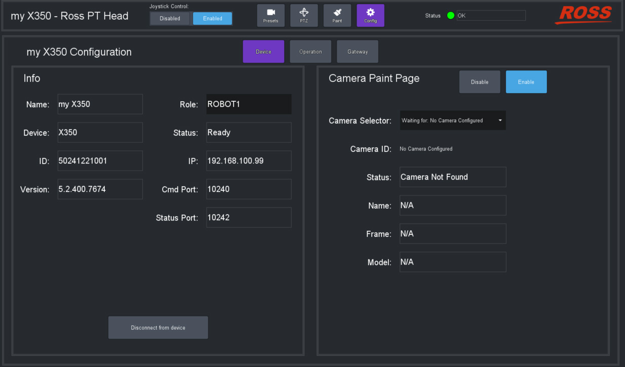
Figure 1 - Config Page (with Device tab selected)
Device Settings
The Device tab contains information and settings pertaining to the PT head, and to the camera.
It includes the PT head Info area (see page 32) and the Camera Paint Page area (see page 33).
Info Area
The Info area (Figure ??) displays information about the PT head. It also enables you to disconnect from the head.
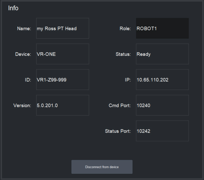
Figure 2 - Info Area
The Info area includes the following:
- Name — The name of the PT head in DashBoard, as defined when the head was added to DashBoard.
- Device — The device type (CAMBOT, VR-ONE, VRONE, X300, X350, or VR600).
- ID — For Furio and X-series robots, the serial number is displayed. For CamBot robots, the Robot ID as defined by the CamBot Translation service is displayed.
- Version — The version of firmware on the PT head.
- Role — The Role setting is not currently operational.
- Status — The operational status of the PT head controller (the PT Head Control Plugin).
- IP — The IP address of the PT head (for Furio and X-series robots), or of the computer running the CamBot Translation service, typically a Robotics Server (for CamBot robots).
- Cmd Port — The number of the command port.
- Status Port — The number of the status port.
- Disconnect from device — Tap this button to sever communication between DashBoard and the PT head. The Disconnected from device dialog box appears. It contains a Reconnect button. DashBoard and the head remain disconnected until you tap the Reconnect button.
Camera Paint Page Area
In the Camera Paint Page area (Figure ??) you can enable or disable the Paint page, which contains controls for adjusting camera paint settings. You can also select which camera is to be painted, and view information about the selected camera.
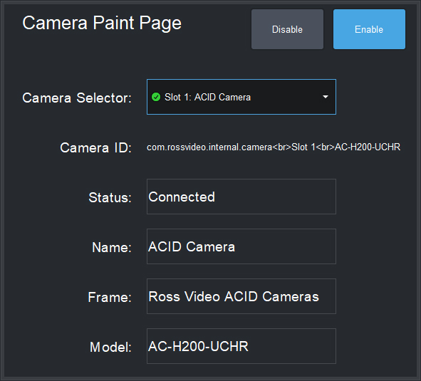
Figure 3 - Camera Paint Page Area
The Camera Paint Page area includes the following:
-
Disable and Enable buttons — When Enabled , the PT Head Control interface includes a Paint button. To access the Paint page, tap the Paint button.

-
Camera Selector — Enables you to select which camera is to be painted. Select the camera that is mounted to the PT head.
-
Camera ID — Displays connection information about the selected camera, including the Slot number within the DashBoard frame that lists the camera, and the camera model.
-
Status — Displays the operational status of the selected camera.
-
Name — Displays the name of the selected camera.
-
Frame — The name of the node in the DashBoard tree through which you can access controls for the selected camera.
-
Model — Displays the model number of the selected camera.
For more information about the Paint page, see “Paint Page”.
Operation Settings
The Operation tab contains information and settings related to the PT Head Control interface.
It includes the Joystick configuration area and the Interface configuration area.
Joystick Area
The Joystick configuration area (Figure ??) enables you to configure how the system responds to joystick input. It also enables you to set the level of detail recorded in system logs.
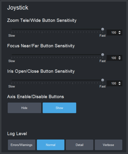
Figure 4 - Joystick configuration area
The Joystick configuration area includes the following settings:
-
Zoom Tele/Wide Button Sensitivity — Defines how far the zoom axis moves when you tap the Tele button or the Wide button on the PTZ page .
-
Focus Near/Far Button Sensitivity — Defines how far the focus axis moves when you tap the Near button or the Far button on the PTZ page .
-
Iris Open/Close Button Sensitivity — Defines how far the iris axis moves when you tap the Open button or the Close button on the PTZ page .
-
Axis Enable/Disable Buttons — Hide or Show the Enabled and Disabled buttons on the PTZ page. For more information about the Enabled and Disabled buttons, see “Configure Axis Behavior”.
-
Log Level — Sets the level of detail recorded in system activity logs. More intensive logging consumes CPU capacity and results in more logging data.
The default setting is Normal . There is no need to adjust the logging level unless requested to do so by Ross Video.
Interface Area
The Interface area (Figure ??) includes settings related to the behavior of the user interface.
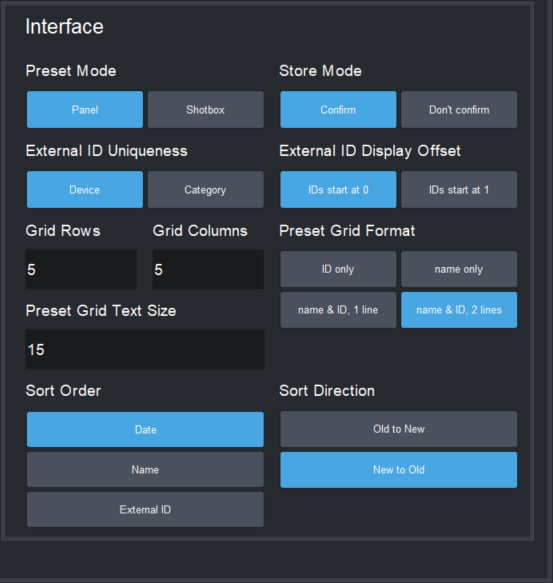
Figure 5 - Interface area
The Interface configuration area includes the following settings:
-
Preset Mode — Defines the behavior of the Preset page:
- Panel mode — In this mode, you tap a preset to select it, and then tap an action button (Cut , Run , Clone , Update , Edit , or Delete ) at the bottom of the Presets page. When you select a preset, the border of the preset button turns purple.
- Shotbox mode — In this mode, you tap an action button at the bottom of the Presets page to enter an action mode (Cut , Run , Alt , Clone , Update , Edit , or Delete ), and then tap the preset to which you want to apply the action.
-
External ID Uniqueness — Sets the scope within which External IDs are kept unique:
- Device — No two External IDs for a device can be identical.
- Category — No two External IDs within a preset category can be identical. An External ID may be used in multiple categories.
-
Grid Rows — Sets the number of horizontal rows of preset buttons displayed on the Presets page. Specify the number and then tap ENTR .
-
Grid Columns — Sets the number of vertical columns of preset buttons displayed on the Presets page. Specify the number and then tap ENTR .
-
Preset Grid Text Size — Defines the size of text on preset buttons (4 - 20 ). Specify the size and then tap ENTR .
-
Sort Order — Specifies the criterion for arranging preset buttons on the Presets page. You can sort by the preset creation time (Date ), by the preset Name , or by the External ID .
-
Store Mode — Defines whether the operator has an opportunity to modify default options that are otherwise applied, each time a new preset is created.
-
If Store Mode is set to Confirm , the operator can review and modify Preset Options when they add or clone a preset. When the operator updates a preset position, the CONFIRM UPDATE dialog box appears.
-
If Store Mode is set to Don't confirm , default Preset Options are automatically stored with the preset. If the operator updates a preset position, the update is applied immediately without a confirmation message. If the operator clones a preset, a current date stamp is added to the name of the cloned preset.
tipTo view/modify the default options for all new presets, tap the Presets button, and then tap Edit Defaults .
-
-
External ID Display Offset — Sets the lowest possible External ID number that the PT Head Control interface can display, as either as 0 or 1 .
This feature enables you to align the numbering of presets between the PT Head Control interface and external controllers, so the same number is displayed for a given preset. For example, if this setting is 0 and you change it to 1 , all existing External IDs are incremented by 1 before they are displayed in the PT Head Control interface.
This setting is an aesthetic choice that affects only the display of External ID values in the PT Head Control interface. It does not affect how External IDs are stored in DashBoard or on the PT head. You can change this setting at any time without affecting the ability to recall presets.
tipFor many external VISCA controllers, such as Carbonite, preset numbering starts at 1 . If such a VISCA controller recalls preset 1 , the first preset is recalled, regardless of whether the PT Head Control interface shows it as preset 0 or 1 . To avoid confusion, when using an external VISCA controller we recommend you set External ID Display Offset to match the controller’s numbering.
-
Preset Grid Format — Defines what text appears on preset buttons, and how it is arranged:
-
ID only — The External ID of the preset is displayed
-
Name only — The preset name is displayed
-
Name & ID, 1 line — The top line displays the External ID of the preset, followed by a colon (:) and the preset name.
-
Name & ID, 2 lines — The top line displays the External ID of the preset only. Subsequent lines display the preset name.
noteRun duration (in seconds) is displayed in yellow text, as the final line on all preset buttons.
-
-
Sort Direction — Specifies whether preset buttons on the Presets page are displayed in the order of most to least, or least to most. The options available depend on the Sort Order setting:
- Date — The options are Old to New , and New to Old .
- Name — The options are A to Z , and Z to A .
- External ID — The options are Low to High , and High to Low .
Gateway Settings
The Gateway Settings page has settings for establishing a communication gateway, to enable external systems to control the PT head.
VISCA Gateway
VISCA Gateway settings (Figure ??) enable you to open a server port to connect VISCA controllers, such as a Carbonite switcher, to the PT head via the PT Head Control plugin.
External VISCA controllers can directly control the pan, tilt, zoom and focus axes. They can also store presets and recall them, by referencing external IDs assigned to presets. The communication protocol is serial VISCA over TCP. Only a subset of VISCA commands is supported. For more information about VISCA control and supported VISCA commands, contact Ross Video Technical Support.
This VISCA gateway implementation is not compatible with the legacy PIVOTCam Control Panel.
On the Operation tab of the Config page, you can configure whether the external numbering of presets starts at 0 or 1 (External ID Display Offset ). The setting is purely aesthetic, and can be changed at any time. For many external VISCA controllers, such as Carbonite, preset numbering starts at 1 . If such a VISCA controller recalls preset 1 , the first preset is recalled, regardless of whether the PT Head Control interface shows it as preset 0 or 1 . To avoid confusion, when using an external VISCA controller we recommend you set External ID Display Offset to match the controller’s numbering. For more information, see “Interface Area”.
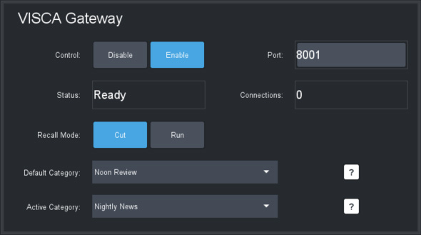
Figure 6 - VISCA Gateway settings
VISCA Gateway settings include the following:
-
Control — To open a server port, set Control to Enable .
-
Port — The port number. Can be edited only when Control is set to Disable .
-
Status (read-only):
- Closed — The port is closed, either because the gateway is disabled or because DashBoard is not connected to the target PT head.
- Ready — The port is open, but no controllers are currently connected to it.
- Connected — The port is open and one or more controllers are connected to it.
- Error — Typically means that the selected port is unavailable. For example, it may be in use by a different service or as a gateway for a different PT head.
-
Connections (read-only) — When status is Connected , shows how many connections are established.
-
Recall Mode :
-
Cut — When a VISCA command recalls a preset, a CUT operation is performed. All controlled axes move to their preset destinations as quickly as possible.
-
Run — When a VISCA command recalls a preset, a RUN operation is performed. All controlled axes reach their preset destinations at the same time. The duration of the preset recall is defined in the preset. For more information, see “Working with Presets”.
noteIf a preset recall request submitted through the gateway is rejected, the recall fails and no warning message appears, even if the Presets page is visible. A recall action may be rejected for various reasons such as insufficient time allotted to run the preset or if one or more required axes are disabled.
-
-
Default Category — Specifies the category where new presets are to be stored when a store preset command is sent to the gateway and no existing preset with the same external ID already exists.
-
Active Category — Specifies the category where DashBoard searches for an existing preset with the requested external ID when a store or recall preset command is sent to the gateway. Valid only when External ID Uniqueness in the Interface area of the Operation tab is set to Category . For more information, see “Interface Area”.
If a VISCA store operation causes a new preset to be created, the name of the new preset is Remote <time_stamp> . For example, Remote 2202-01-07 13:26:42 .
Storing and Recalling Presets through VISCA Gateway
Each preset on the PT head has an external ID. The results of storing and recalling presets through VISCA commands varies depending on the External ID Uniqueness setting in the Interface area of the Operation tab. This setting specifies either that all external IDs on the head must be unique (Device option), or that identical external IDs can exist on the head as long as each ID is in a different category (Category option).
The following table describes how a PT head responds to Store and Recall actions requested through VISCA commands.
Table 1
| Action | External IDs Unique by Category | External IDs Unique by Device |
|---|---|---|
| Store |
|
|
| Recall | If a preset with the requested external ID exists in the Active Category, recall this preset. | If a preset with the requested external ID exists on the PT head, recall this preset. |
Joystick Control through VISCA Gateway
Joystick control is shared between the PT Head Control plugin and any controllers connected through the VISCA gateway.
If joystick control is currently enabled for the plugin, axes can be controlled using the PT Head Control interface, a joystick connected to DashBoard, or a controller connected to the VISCA gateway. A new command from any of these devices overrides previous commands.
If joystick control is currently disabled for the PT Head Control plugin, any velocity controls sent through the VISCA gateway are rejected.
This VISCA implementation includes a special command that enables a VISCA controller to activate the enable/disable joystick control on the PT Head Control plugin. For more information, contact Ross Video Technical Support.