Add ing USB Controllers
You can set up USB controllers such as joysticks, button pads, and game controllers, to select camera systems and to operate head movements (pan and tilt) and lens functions (focus, zoom, and iris). USB controllers working in conjunction with the PT Head Control Plugin can also control shading and paint settings on DashBoard-controllable cameras such as ACID cameras and supported third-party cameras.
This section describes how to set up one or more USB joysticks or other USB controllers to select and control Ross PT heads and cameras/lenses mounted to them.
USB joystick controls are not supported for use with a proxy server. They are designed for systems where the control computer is connected directly to the PT head over an IP network.
The main steps are as follows:
- “Add a USB Controller in DashBoard”
- “Add Device Classes, and Map Controls to Parameters”
- “Map Device Classes to Controllers”
- “Configure Relationship Between Camera System Selection and UI Focus”
- “Map Buttons for Camera Selection”
Add a USB Controller in DashBoard
To add a USB controller:
-
Close DashBoard.
-
Plug the USB controller into a USB port on the DashBoard computer.
-
Start DashBoard.
When DashBoard starts, it detects the controller.
tipDashBoard can detect the controller only if the controller is plugged in when DashBoard starts.
-
In DashBoard, on the File menu, select New, and then select Other .
The New dialog box appears (Figure ??).
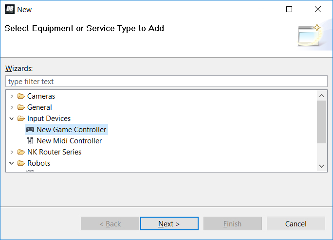
Figure 1 - Adding a USB controller
-
In the Wizards list, expand Input Devices , select New Game Controller , and then tap Next .
The New Game Controller Connection dialog box appears (Figure ??).
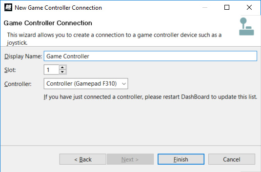
Figure 2 - Connecting to a USB controller
-
In the Display Name box, type a name for the controller.
-
In the Controller list, select the type of USB controller you plugged in.
noteIf the controller type is not on the list, either it was not detected or it is already registered in DashBoard.
-
Click Finish .
A node for the controller appears within the Game Controllers node in the DashBoard Component Tree . The node has the name you specified.
Add Device Classes, and Map Controls to Parameters
A USB controller typically has buttons and axis controls. A button is either on or off, and therefore returns one of two data values. An axis control, such as a joystick, can return any value within a range of data values, depending on how far the joystick is moved in one direction or the other.
You can configure each axis control on the USB controller to operate a robotic axis or a control that accepts a continuous range of data values, such as a paint control.
Additionally, you can configure buttons to return single values. For example, if you often want to pan right or left at half speed, you can configure one button to apply a panning speed value of -50 while pressed, and another to apply a panning speed value of 50 (pan axis range is -100 to 100).
This section describes how to map a wide variety of commonly-used axis controls and button controls. You can decide which controls you want to map, based on your preferences and the available physical controls on your USB device(s).
To add device classes and map controls to DashBoard parameters (OIDs):
-
In the DashBoard Component Tree , expand the Game Controllers node, and then double-tap the controller node you added.
The configuration interface for the controller appears (Figure ??). The ptzjoystick Device Class is present by default.
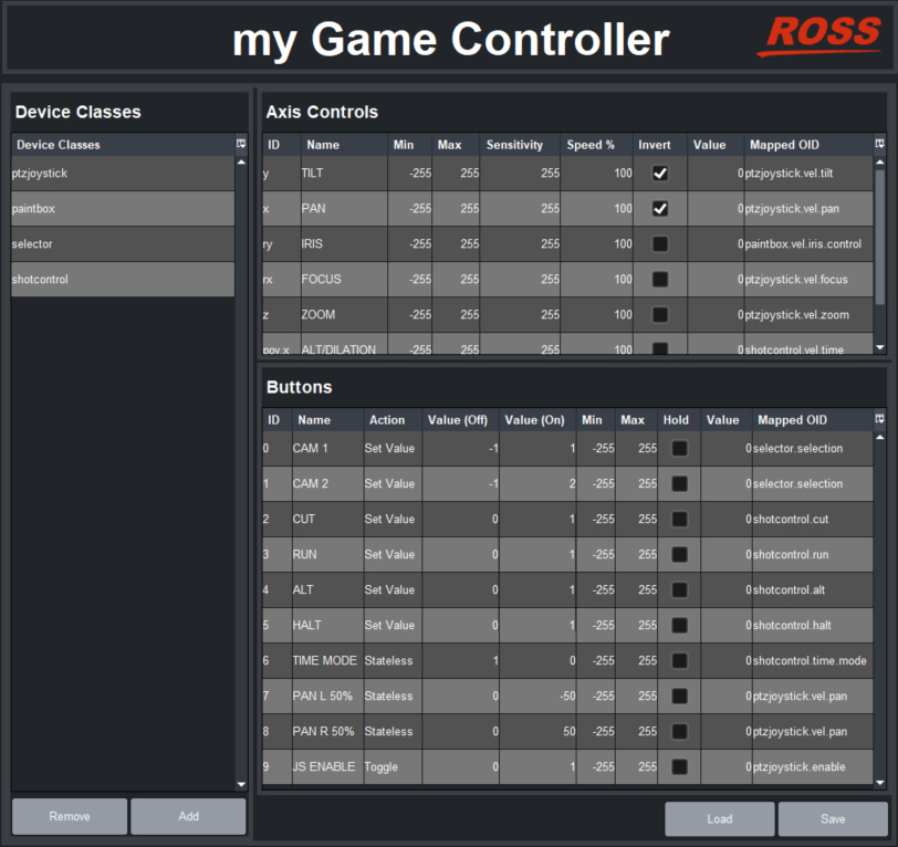
Figure 3 - Mapping USB controller inputs (shown with Device Classes added and controls mapped to OIDs)
-
The number and types of axis controls and buttons vary between different models of USB controllers.
-
If you want this controller to operate the lens iris and/or camera shading and paint controls (DashBoard-controllable cameras only), in the Device Classes list, add a new device class and name it paintbox .
-
If you have multiple PT heads and want to use buttons on this controller to select which head to operate, in the Device Classes list, add a new device class named selector .
-
If you want to use buttons on this controller for shot controls (cut, run, alt, halt, and preset duration controls), in the Device Classes list, add a new device class named shotcontrol .
-
In the Axis Controls table, create mappings for the velocity parameters that you want the USB controller’s axis controls (such as joysticks) to operate.
When you create mappings, you link data items reported by the controller to parameters (OIDs) in the PT Head Control interface.
tipTo determine which Axis Controls and Buttons correspond to physical controls on the controller, move the controller’s joystick and push its buttons while observing changes in the Value column.
For an example showing the Axis Controls mapping table completed, see Figure 3.
tipIf you are configuring multiple controllers and dividing the control functions between them, the controls within each device class must be assigned to a single controller. The name of each parameter OID starts with the name of its device class (selector , ptzjoystick , paintbox , or shotcontrol ).
The following table lists parameters that are commonly mapped to axis controls.
Table 1
| Parameter (Mapped OID) | Description |
|---|---|
| ptzjoystick.vel.tilt | Tilt axis |
| ptzjoystick.vel.pan | Pan axis |
| ptzjoystick.vel.zoom | Zoom axis (lens zoom) |
| ptzjoystick.vel.focus | Focus axis (lens focus) |
| paintbox.vel.iris.control | Iris axis (lens iris) |
| paintbox.vel.black.master_black | Master Black paint control (DashBoard-controllable cameras only) |
| paintbox.vel.black.g | Green Ped paint control (DashBoard-controllable cameras only) |
| paintbox.vel.black.b | Blue Ped paint control (DashBoard-controllable cameras only) |
| paintbox.vel.black.r | Red Ped paint control (DashBoard-controllable cameras only) |
| paintbox.vel.whitebalance.gain.g | Green Gain paint control (DashBoard-controllable cameras only) |
| paintbox.vel.whitebalance.gain.b | Blue Gain paint control (DashBoard-controllable cameras only) |
| paintbox.vel.whitebalance.gain.r | Red Gain paint control (DashBoard-controllable cameras only) |
| shotcontrol.vel.time | Time adjustment axis. This parameter enables the operator to increase/decrease the duration of a preset, either before it is run or during recall. This parameter works in conjunction with the shotcontrol.time.mode parameter, which can be mapped to a button:
|
| ptzjoystick.vel.time | Time adjustment axis. This parameter enables the controller to change the speed of robot movement while a preset is being recalled (time dilation). Alternatively, you can use shotcontrol.vel.time in conjunction with shotcontrol.time.mode. |
-
Relevant columns in the Axis Controls mapping table are as follows:
-
ID - The ID of the control, as reported by the controller. This is not configurable.
-
Name - You can name each control for future reference (optional).
-
Min and Max - Defines the range of data values sent to the DashBoard parameter. When the control is in a neutral position, the data value is halfway between Min and Max . For example, if Min is -100 and Max is 200 , the neutral value is 50 .
tipDashBoard automatically scales the data value to suit the data range of the associated parameter. You do not need to match Min and Max to the lowest and highest parameter values.
-
Speed% — Scales the data values, to make them change more or less gradually. For example, if you use a joystick to control a paint velocity parameter such as paintbox.vel.black.master_black , you might set Speed % to 10 . When you push the joystick all the way, the value changes at one-tenth the default rate. This enables you to see the effect more easily as you change the value.
-
Sensitivity — Defines the number of steps between each end of the data range and the controller’s neutral position. For example, if Min is -100 , Max is 100 , and Sensitivity is 20 , then the value changes by increments of 5 . The range of values starts at - 100 (-100 , -95 , -90 , etc.) and continues to 100 .
-
Invert - When selected, reverses the direction of joystick motion required to move the axis. For example, if the PT head and camera are ceiling mounted, select Invert for pan and tilt so when you move the joystick, the head and camera move as desired.
-
Value - Shows the current data value reported by the controller. This is useful for testing.
-
Mapped OID - Specify the parameter OID from the PT Head Control interface to be mapped to the control.
-
-
In the Buttons table, create mappings for the parameters that you want the USB controller’s buttons to operate.
When you create mappings, you link data items reported by the controller to parameters (OIDs) in the PT Head Control interface.
tipTo determine which Axis Controls and Buttons correspond to physical controls on the controller, move the controller’s joystick and push its buttons while observing changes in the Value column.
For an example showing the Buttons mapping table completed, see Figure 3.
tipIf you are configuring multiple controllers and dividing the control functions among them, the controls within each device class must be assigned to a single controller. The name of each parameter OID starts with the name of its device class (selector , ptzjoystick , shotcontrol , or paintbox ).
The following table lists parameters that are commonly mapped to button controls.
Table 2
| Parameter (Mapped OID) | Description |
|---|---|
| selector.selection | Camera system selection, for systems that include multiple cameras/robots. Map this parameter to a set of buttons to be used for selecting the camera system to be controlled. Each row in the Buttons table corresponds to a button on the controller. For each button you want to assign as the selector for a camera system, do the following:
|
| shotcontrol.cut | When pressed, the button performs a Cut action:
|
| shotcontrol.run | When pressed, the button performs a Run action:
|
| shotcontrol.alt | When pressed, the button performs an Alt action:
|
| shotcontrol.halt | When pressed, stops all movement of the PT head and camera controls. To map shotcontrol.halt:
|
| shotcontrol.time.mode | This parameter works in conjunction with the shotcontrol.vel.time parameter, which is an axis parameter that increases/decreases the duration of a preset. The shotcontrol.time.mode parameter enables the operator to choose whether shotcontrol.vel.time applies before the preset runs (alt duration), or while the preset is running (time dilation):
|
| shotcontrol.vel.time | Time axis. This parameter works in conjunction with shotcontrol.time.mode, enabling the controller to change either the duration of a preset before it is recalled (alt duration), or change the speed of robot movement while a preset is being recalled (time dilation). You can configure one or more buttons to apply a speed value to the time axis (value range -100 to 100). To map ptzjystick.vel.time to a button:
|
| ptzjoystick.vel.tilt | Tilt axis. You can configure one or more buttons to apply a speed value to the tilt axis (value range -100 to 100). To map ptzjystick.vel.tilt to a button:
|
| ptzjoystick.vel.pan | Pan axis. You can configure one or more buttons to apply a speed value to the pan axis (value range -100 to 100). To map ptzjystick.vel.pan to a button:
|
| ptzjoystick.vel.zoom | Zoom axis. You can configure one or more buttons to apply a speed value to the zoom axis (value range -100 to 100). To map ptzjystick.vel.zoom to a button:
|
| ptzjoystick.vel.focus | Focus axis. You can configure one or more buttons to apply a speed value to the focus axis (value range -100 to 100). To map ptzjystick.vel.focus to a button:
|
| ptzjoystick.vel.time | Time axis. This parameter enables the controller to change the speed of robot movement while a preset is being recalled. To map ptzjystick.vel.time to a button:
|
| paintbox.iris.control | Iris control. Note: Iris control through the paintbox.iris.contol parameter is available only if the PT head is not configured to control iris through the PTZ page. Configure one button to increase the value and another to decrease it:
|
| ptzjoystick.enable | Enables/disables joystick control of the robot. To map ptzjoystick.enable:
|
-
Relevant columns in the Buttons mapping table are as follows:
-
ID - The ID of the control, as reported by the controller. This is not configurable.
-
Name - You can name each control for future reference (optional).
-
Action - The type of action to be performed when the button is pressed.
-
Value (Off) - The value assigned to the parameter, under the following conditions:
- If Action is set to Toggle , each time the button is pressed the parameter value switches (toggles) between Value (Off) and Value (On) .
- If Action is set to Stateless , Value (Off) is the value of the parameter when the button is released.
- If Action is set to Set Value , Value (Off) is ignored.
- For all other Action settings, Value (Off) is not applicable.
-
Value (On) - The value assigned to the parameter, under the following conditions:
- If Action is set to Toggle , each time the button is pressed the parameter value switches (toggles) between Value (Off) and Value (On) .
- If Action is set to Stateless , Value (On) is the value of the parameter while the button is depressed.
- If Action is set to Set Value , Value (On) is the value assigned to the parameter each time the button is pressed.
- For all other Action settings, Value (On) is not applicable.
-
Value - Shows the current data value reported by the controller. This is useful for testing.
-
Mapped OID - Specify the parameter OID from to be mapped to the control.
-
-
If you want to save the mappings in a file that can be loaded onto other DashBoard computers, click the SAVE button and specify a file name and path.
noteThe mappings are specific to the controller(s) you configured. You can use the mappings on other DashBoard computers only if their controllers are the same model, or report the exact same controls.
Map Device Classes to Controllers
PT head and camera functions that are commonly controlled by a USB controller fall into four groups; camera selection, camera motion (pan, tilt, zoom, and focus), shot controls (cut, run, alt, halt, and preset duration controls), and paintbox controls (lens iris). Depending on the USB controller(s) available, you can control all functions with a single controller, or add a separate controller for each group of functions.
To map device classes to one or more controllers:
-
In the Component Tree , within the DashBoard Services node, double-tap Device Class Mappings .
The Device Class Mappings interface appears (Figure ??).
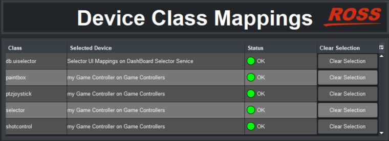
Figure 4 - Device Class Mappings for a USB controller (shown populated with mappings)
-
In the db.uiselector row, set Selected Device to Selector UI Mappings on DashBoard Selector Service .
tipIf a class you want to map is already mapped, click Clear Selection and then map it to the controller.
-
If you plan to use the controller to adjust lens iris, in the paintbox row set Selected Device to the controller you are configuring.
-
If you plan to use the controller to move robots/cameras (pan, tilt, zoom, focus, iris), in the ptzjoystick row set Selected Device to the controller you are configuring.
-
If your system has multiple PT heads and you plan to use buttons on the controller to select cameras/robots in DashBoard, in the selector row set Selected Device to the controller you are configuring.
-
If you plan to use shot controls (cut, run, alt, halt, and preset duration controls), set Selected Device to the controller you are configuring.
Configure Relationship Between Camera System Selection and UI Focus
You can configure how the user interface interacts with the controller, to achieve your choice of the following options:
- The controller can select and control camera systems ONLY IF the PT Head Control interface is the active DashBoard application (in focus).
- The controller can select and control camera systems regardless of what DashBoard application is active (in focus).
- If a controller button configured to open a device view or panel is pushed, that device view or panel becomes active (in focus).
To configure the relationship between camera selection and UI focus:
-
In the Component Tree , expand the DashBoard Services node, and then double-tap Selector UI Mappings .
The Selection Mapping interface appears (Figure ??).
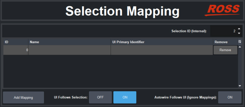
Figure 5 - UI Follow and Autowire settings
-
Choose one of the following options and tap the corresponding button:
-
Autowire Follows UI ON
If you select this option, you cannot use the controller to select and control camera systems unless the PT Head Control interface is the active DashBoard application (in focus).
This option helps prevent accidental movement of cameras while the operator is using other DashBoard panels or device views. It also ensures that the PT Head Control interface is always readily available while you are controlling camera systems.
-
UI Follows Selection OFF
If you select this option, you can use the controller to select and control camera systems regardless of which panel or device view is active (in focus).
This option enables you to use the PT Head Control interface and other DashBoard panels or device views for other tasks while you use the controller to select and control camera systems.
-
UI Follows Selection ON
If you select this option, whenever a configured button opens a DashBoard panel or device view, that panel or device view becomes active (in focus). If the PT Head Control interface is active and you press a controller button to open a different panel or a device view, the PT Head Control interface loses focus.
Use this option if you want to configure otherwise unassigned controller buttons to open DashBoard panels and device views on demand, such as Carbonite control, or the PT Head Control interface.
-
Map Buttons for Camera Selection
This procedure applies if your system has multiple camera systems and you want to configure controller buttons to select them.
To map camera selector buttons:
-
In the Selection Mapping interface (Figure ??), tap the Add Mapping button.
A new mapping row appears in the Selection Mapping table.
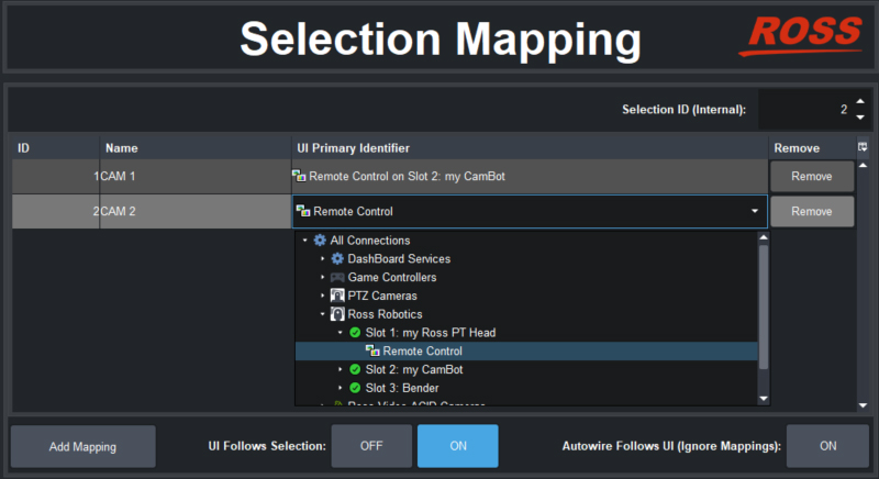
Figure 6 - Mapping Camera Selector buttons to Camera Systems
-
In the new mapping, set ID to the camera ID number for a camera system. Each mapping requires a unique ID.
tipYou defined the camera ID numbers as Value on settings for buttons, in a previous procedure (“Add Device Classes, and Map Controls to Parameters”).
-
Specify a Name for the mapping (optional).
-
For UI Primary Identifier , navigate to Remote Control for the camera system to be selected.
-
Repeat the preceding steps for each camera selector button you want to configure.