Configuration Settings and On-Screen Menu
This section contains topics about controls that are available on the Config page. To open the main Configuration Settings page, tap the Config button.
Depending on the model of camera, the main Configuration Settings page includes some or all of the buttons shown in Figure ??. Some camera models have an Video Mode button instead of an Audio/Video button.

Figure 1 - Buttons at the top of the Configuration Settings page
- Camera — Opens the Camera Settings page, which includes Camera Info settings and Camera Options settings. For more information, see “Camera Settings Page”.
- Audio/Video — Opens the Audio/Video Settings page, which includes SDI Video settings and Audio settings. For more information, see “Audio/Video Settings Page”.
- Video Mode — Opens the Video Mode page, which enables you to set video modes for SDI Video, Mainstream Video, and Substream Video. For more information, see “Video Mode Settings Page”.
- Operation — Opens the Operation Settings page, which includes Joystick settings and Interface settings. For more information, see “Operation Settings Page”.
- Gateway — Opens the Gateway Settings page, which includes tally interface settings, as well as settings for establishing VISCA and/or Furio communication gateways that enable external systems to control the camera. For more information, see “Gateway Settings Page”.
- Open On-Screen Menu — Opens the Menu Control page, which enables you to adjust camera settings using the on-screen menu. For more information, see “On-Screen Menu”.
- Pan/Tilt Reset — Returns the camera to a known home position.
Some features described in this section are not available on all cameras. The selection of features and the appearance of the interface may vary between camera models. Unless stated otherwise, figures and feature descriptions in this section describe the interface as it appears for Ross Video PTZ-12G cameras. For information about configuration controls for other camera types, refer to the user manuals for those cameras.
Camera Settings Page
The Camera Settings page includes the Camera Info area and the Camera Options area (Figure ??).
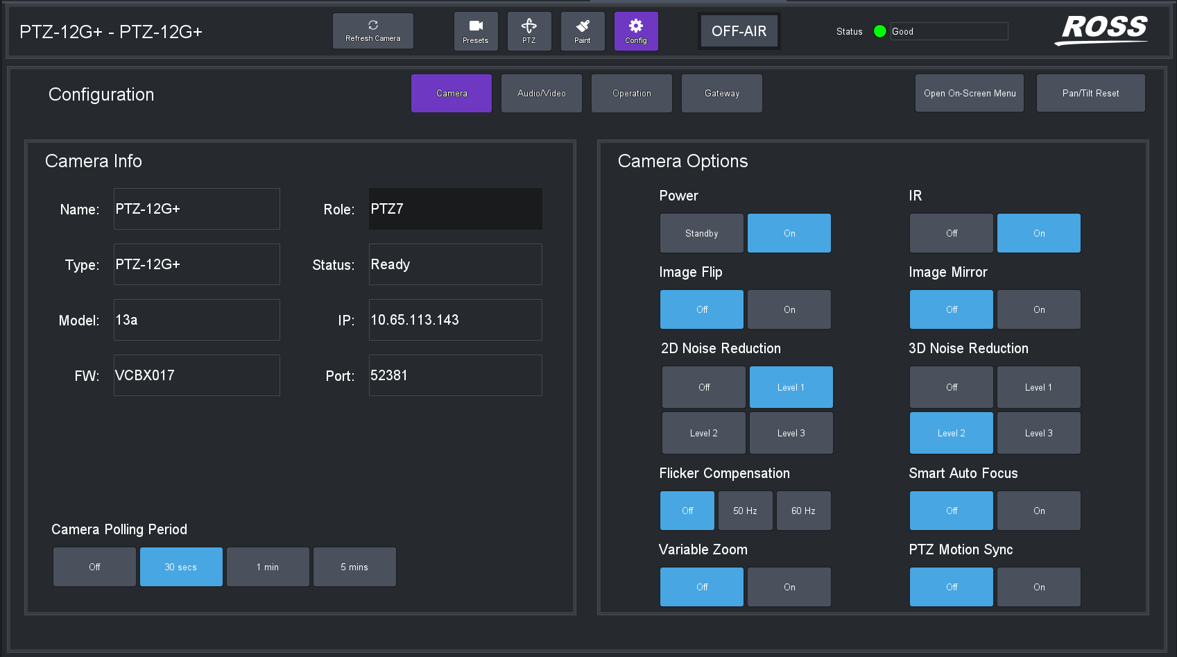
Figure 2 - Camera Settings page for a PTZ-12G+ camera (PTZ-NDI has same settings)
Configuration settings vary between camera models. Some settings shown and described in this section may not apply to your camera.
Camera Info Area
The Camera Info area displays camera information, as provided by the camera (Figure ??).
This section describes camera information provided by Ross Video PTZ-12G cameras. Information provided by other types of PTZ cameras may vary.
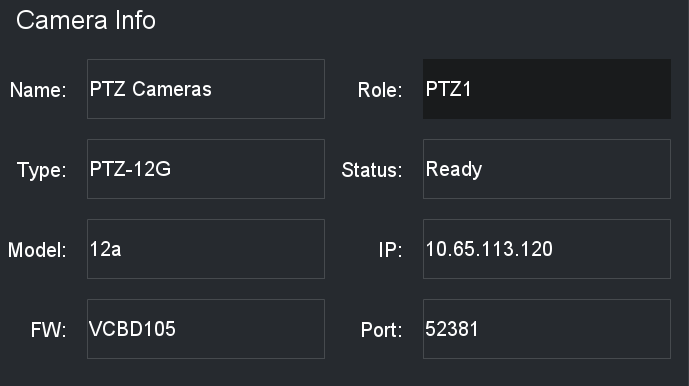
Figure 3 - Camera Info area for a PTZ-12G+, PTZ-12G, or PTZ-NDI camera
Name
The name of the camera, as it appears in the DashBoard tree and in the PTZ Camera Control Plugin. The camera name is defined when you add the camera to DashBoard.
Role
A unique identifier for the camera, as a reference to enable the capture and storage of thumbnail images in camera control systems such as SmartShell, via the Furio gateway.
The Role value can be edited. By default, the Role value is PTZx , where x is the camera’s slot number in the DashBoard tree. Other device types, such as Ross Video pan & tilt heads, have different default prefixes instead of PTZ . It is important to ensure that all Role values are unique, and conform to the requirements of the system(s) using them.
Valid characters are limited to alpha-numeric characters and the underscore ( _ ) symbol. Other characters are automatically removed.
Notes : If you set a Role value that is already in use for another camera, the new Role value is ignored, and the previous camera retains its role value.
Type
The type of camera, such as Ross Video PTZ-12G+ , PTZ-12G or PTZ-NDI , PIVOTCam-SE , Sony BRC-H900 , Sony BRC-X1000 , Sony ILME-FR7, S ony BRC-AM7, Panasonic AW-UE15 0, AW-UE160, AW-HR1 40 , Lumens VC-A71P , Lumens VC-A71PN , Canon CR-N300 , Canon CR-N500 , or CR-X300 .
Status
The operational status of the camera.
Model
Additional model number, as reported by the camera.
IP
The IP address of the camera.
FW
The version(s) of firmware currently installed on the camera.
Port
The port number used to communicate with the camera.
Camera Options Area
The Camera Options area (Figure ??) includes camera settings, some of which may be specific to the model of camera you are configuring. Some settings described in this section of the manual are not available on all camera models.
For detailed information about camera settings, consult your camera manual.
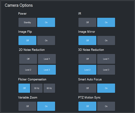
Figure 4 - Camera O ptions area for a PTZ-12G+, PTZ-12G, or PTZ-NDI camera
Power
Tap On to turn the camera on. Tap Standby to put the camera in standby (non-operational) mode.
IR
Controls whether the camera can receive commands from the IR (infra-red) remote control unit.
Tap On to turn on the IR receiver. Tap Off to turn off the IR receiver.
Image Flip and Image Mirror
Image Flip reverses the video image vertically.
Image Mirror reverses the image horizontally.
Tips :
- Configure the Image Flip and Image Mirror settings before you create any presets. Changing camera orientation makes existing presets useless.
- For cameras mounted upside-down on the ceiling, set Image Flip and Image Mirror to On .
- If you change the Image Flip and Image Mirror settings remember to configure the Horizontal Axis and/or Vertical Axis joystick settings (Config > Operation > Joystick ) so the direction of joystick motion corresponds with the direction of camera movement.
Ceiling Mount
For some cameras, such as Sony cameras and PIVOTCam-SE cameras, a Ceiling Mount setting (Figure ??) is shown instead of Image Flip and Image Mirror . When On , Ceiling Mount rotates the camera image 180 degrees.

Figure 5 - Ceiling Mount setting
If you change the Ceiling Mount setting for a Sony camera, you must power cycle the camera afterwards to apply the change. All presets are erased.
Tips :
- Configure the Ceiling Mount setting before you create any presets. Changing camera orientation makes existing presets useless.
- For cameras mounted upside-down on the ceiling, set Ceiling Mount to On .
- If you change the Ceiling Mount setting, remember to configure the Horizontal Axis and Vertical Axis joystick settings (Config > Operation > Joystick ) so the direction of joystick motion corresponds with the direction of camera movement.
2D Noise Reduction
2D noise reduction creates clearer images in low light conditions through temporal noise reduction, which is based on analysis of differences between video frames.
You can turn this feature Off or select one of three levels from Level 1 (weak) to Level 3 (Strong).
3D Noise Reduction
3D noise reduction creates clearer images in low light conditions through both temporal and spatial noise reduction:
-
Temporal noise reduction is based on analysis of differences between video frames.
-
Spatial noise reduction reduces noise within each video frame without comparison to other frames.
You can turn this feature Off or select one of three levels from Level 1 (weak) to Level 3 (Strong).
Flicker Compensation
Compensates for light flicker caused by disparity between the video frame rate and the frequency of the AC power supply for lighting.
Smart Auto Focus
Enables face detection and auto focus. When On , Auto Focus focuses mainly on the face.
This setting is available only when the Auto Focus option on the PTZ page is On . For more information, see “Focus Controls”.
When you change this setting, the video feed is briefly interrupted. Tap OK if you wish to proceed.
Variable Zoom
Varies the speed of the pan and tilt axes when you control them manually, based on the zoom position. When the lens is zoomed in, the affected axis moves more slowly. When the lens is zoomed out, the affected axis moves more quickly.
Wiper Connection (CR-X300 only)
The Canon-X300 plugin can be configured to expose controls to activate the wiper mechanism on the camera. To do this, a separate HTTP connection must be established with the camera. When a wiper control connection is successfully established, wiper buttons will be enabled on the Presets and PTZ pages of the plugin.
Configuring the HTTP connection is not necessary if wiper control is not required.
Depending on your setup, you may need to configure HTTP authentication with a username and password. This can only be done when the wiper connection is disabled.
To configure the wiper connection
-
Navigate to the Wiper Control Connection section in the Camera Options area. Refer to Figure ??.
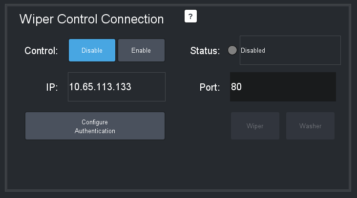
Figure 6 - Wiper Control Connection section
-
Set the Port number to the configured port on the camera.
-
Select Configure Authentication (if required). Refer to Figure ??.

Figure 7 - HTTP Authentication Configuration dialog box
-
Note : The HTTP connection depends on the camera settings and how User Management is set up for the CR-X300:
-
If the Guest User has Camera Control privileges, no authentication is required in DashBoard. Leave the Username and Password fields empty.
-
If the Guest User does not have Camera Control privileges, authentication is required in DashBoard. Enter a Username and Password with Camera Control privileges that match a user account previously set on the camera.
tipTo configure the camera for secure connection, go to System > Server > HTTP Video in the camera Web UI and set Authentication Method to Digest Authentication .
-
-
Select Done to return to Wiper Control Connection .
-
Select Enable in the Control setting.
noteThe camera’s Port connection and IP address display automatically if the camera connection is established on DashBoard already.
To confirm everything works correctly, select either the Wiper or Washer buttons to activate the camera’s wiper and washer functions.
notePresets cannot be recalled while the washer is in operation.
Wiper controls are disabled when the camera is on-air.
Connection status
The connection status indicates whether the wiper link is properly configured and the connection is successfully established.
Connection statuses include the following:
- Disabled — Wiper control is disabled.
- Error — Wiper control is enabled, but not properly configured. Wiper controls are inaccessible and device status displays a warning of “No wiper control.” Refer to Figure ??.

Figure 8 - No wiper control message
-
Status messages provide information on the error, including:
- Failed authentication — Verify that the provided username and password align with a valid set of credentials within the camera control permissions on the connected camera.
- Offlin e - no communication — Confirm that the port matches the port set on the camera.
-
OK — Wiper control is enabled and correctly configured. Wiper controls are accessible in DashBoard.
To set up wiper and washer joystick control
To control the wiper and washer, refer to instructions on setting up a joystick are available in “Adding USB Joysticks or Other USB Controllers”, and Table 2.
Camera Polling
The Camera Polling Period setting allows you to define an interval to poll the camera to pick up changes made by controllers other than DashBoard. Polling is disabled by default. Refer to Figure ??.

Figure 9 - The Camera Polling Period settings
This feature generates a lot of message traffic if enabled. Many PTZ cameras polling on the same network may cause slowdowns.
Configuring Authentication (Panasonic Cameras Only)
To enable communication with a Panasonic PTZ camera that has authentication enabled, configure the required username and password in DashBoard.
To configure authentication:
- In the PTZ Camera Control plugin, navigate to Config > Camera > Configure Authentication .
- In the HTTP Authentication Configuration dialog box, enter the required Usernam e and Password , then tap Done .
Figure 10 - HTTP Authentication Configuration dialog box
For authentication to function correctly:
- The camera must be set to use Digest authentication.
- The user account must have at least Camera Control privileges.
- If available on your camera model, set Wait Time Mode to Mode 2.Tip: It is recommended to enter the credentials in DashBoard before enabling authentication on the camera. Enabling authentication first may prevent DashBoard from connecting, as the camera may reject all HTTP connection attempts.
Refer to the Panasonic camera’s operator manual for model-specific setup instructions
Audio/Video Settings Page
The Audio/Vid eo Settings page includes the SDI Video area and the Audio area (Figure ??).
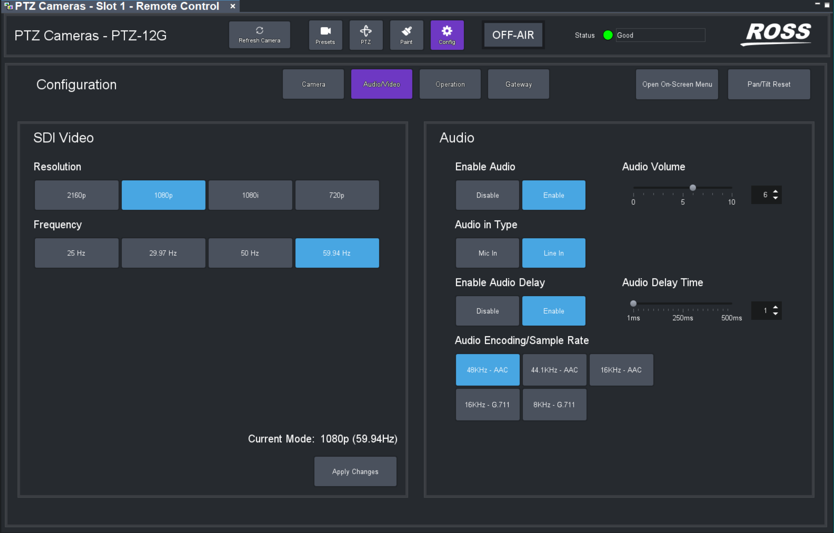
Figure 11 - Audio Video settings page fo r a PTZ-12G camera
SDI Video Area
The SDI Video area (Figure ??) enables you to set the resolution and frequency for SDI video output.
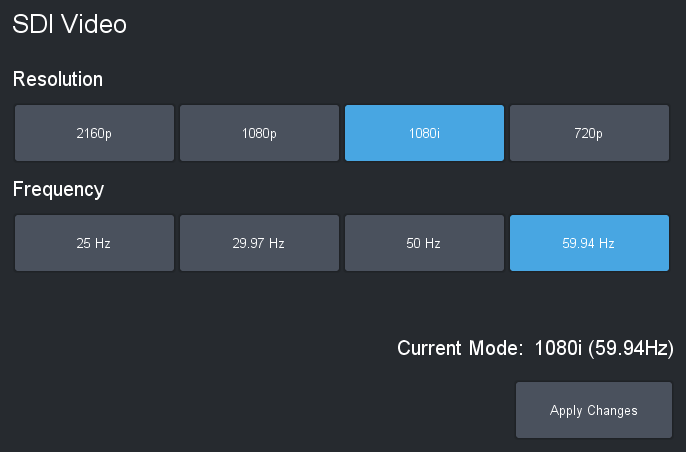
Figure 12 - SDI Video area
Select a Resolution and a Frequency , and then tap the Apply Changes button.
Some combinations of resolution and frequency are non-standard and not supported. The Apply Changes button is available only if the selected video format is supported.
Audio Area
The Audio area (Figure ??) enables you to specify audio input properties.
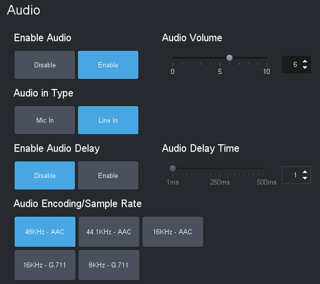
Figure 13 - Audio area
Enable Audio
Enables or disables audio input.
When you Enable or Disable audio input, the video feed is briefly interrupted. Tap OK if you wish to proceed.
Audio Volume
Sets the audio volume from 0 (lowest) to 10 (highest).
This setting is available only when audio is enabled.
Audio in Type
Selects the type of audio input (Mic in or Line in ).
This setting is available only when audio is enabled.
Enable Audio Delay
When enabled, audio is delayed. Use this feature to synchronize audio and video.
To set the delay period, adjust the Audio Delay Time slider or specify a delay value (1 to 500 milliseconds) in the Audio Delay Time box.
This setting is not supported on PTZ-12G+ and PTZ-NDI cameras when NDI|HX video is enabled in the web interface.
Audio Encoding/Sample Rate
Sets the encoding type and sample rate for encoding incoming audio. For SDI video on PTZ-12G cameras, only 48 kHz (AAC) is supported. This setting is not supported on PTZ-12G+ and PTZ-NDI cameras when NDI|HX video is enabled in the web interface.
This setting is available only when audio is enabled.
Video Mode Settings Page
For the PIVOT-SE , the Video Mode page is shown instead of the Audio/Video page.
This allows you to configure the main SDI video and also the mainstream and substream video options for the camera.
Operation Settings Page
The Operation Settings page (Figure ??) includes the Joystick area and the Interface area.
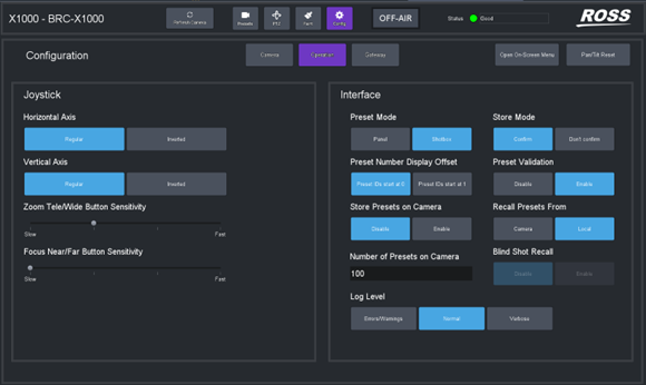
Figure 14 - Operation Settings page for a Sony RBC-X1000 camera
Joystick Area
The Joystick area (Figure ??) includes settings related to joystick behavior, and to the sensitivity of Zoom and Focus buttons on the PTZ page.
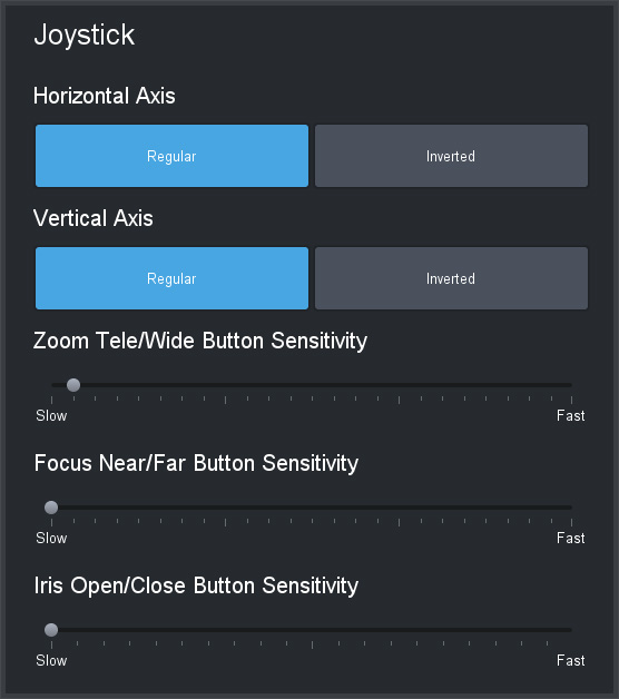
Figure 15 - Joystick area for a Panasonic PTZ camera
Horizontal Axis and Vertical Axis
You can co-ordinate the direction of joystick motion with the direction of camera motion:
-
Horizontal Axis — Determines which direction (right/left) you need to push the joystick to pan the camera right or left.
-
Vertical Axis — Determines which direction (forward/back) you need to push the joystick to tilt the camera up or down.
Use the joystick to move the camera, observe the camera motion, and then adjust these settings as desired.
For PIVOTCam-SE cameras, Sony BRC cameras, and Lumens PTZ cameras, these axis direction settings affect pan and tilt controls in DashBoard and in any external controllers.
For Ross Video PTZ-12G+, PTZ-12G, and PTZ-NDI cameras, Panasonic models, and Sony ILME-FR7 and BRC-AM7 cameras, these axis direction settings apply within DashBoard only, and do not change any settings on the camera or affect control by any external controllers.
Zoom Tele/Wide Button Sensitivity
The Zoom control on the PTZ page includes Tele and Wide buttons that enable you to manually zoom the camera lens. Use the Zoom Tele/Wide Button Sensitivity slider to set how quickly the camera zooms.
Focus Near/Far Button Sensitivity
The Focus control on the PTZ page includes Near and Far buttons that enable you to manually focus the camera lens. Use the Focus Near/Far Button Sensitivity slider to set how quickly the camera focuses.
Iris Open/Close Button Sensitivity (Panasonic, Sony ILME-FR7, and Sony AM7 cameras only)
The Iris control on the PTZ page includes Open and Close buttons that enable you to manually adjust the aperture. Use the Iris Open/Close Button Sensitivity slider to set how quickly the iris opens and closes.
This sensitivity slider affects the behavior of iris controls within DashBoard, but does not change any settings on the camera.
Interface Area
The Interface area (Figure ??) includes settings related to the behavior of the user interface.
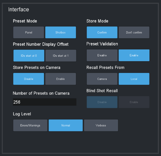
Figure 16 - Interface area
The Blind Shot Recall setting specifies whether you can attempt to recall a shot from the camera when there is no locally stored data in the slot:
- Disable — Empty camera slots cannot be recalled.
- Enable — Empty camera slots can be recalled.
Preset Mode
Tap one of the following Preset Mode buttons to define the behavior of the Presets page:
- Panel — In this mode, you tap a preset to select it, and then tap an action button (Recall , Store , Edit Preset Option s, or Delete ). When you select a preset, the border of the preset button turns purple.
- Shotbox — In this mode, you tap an action button at the bottom of the Presets page to enter an action mode (Recall , Store , Edit Preset Option s, or Delete ), and then tap the preset to which you want to apply the action.
Store Mode
There are two store modes:
- If Store Mode is set to Confirm , the operator can review and modify Preset Options when they store a preset.
- If Store Mode is set to Don't confirm , default Preset Options are automatically stored with the preset.
To access settings to define the default Preset Options:
-
Tap Presets , and then do one of the following:
- If the Store Option s area is visible (top right corner), tap the Edit Defaults button. The Edit Default Preset Options dialog box appears.
- If the Store Options area is not visible, tap the Store button. The Store Options area appears. Tap the Edit Defaults button. The Edit Default Preset Options dialog box appears.
Preset Number Display Offset
Presets are numbered. You can set the numbering to start at 0 or at 1 .
This is an aesthetic choice; changing between ID start at 0 and ID start at 1 does not change how presets are stored in DashBoard or on the camera. The setting can be changed at any time.
For many external VISCA controllers, such as Carbonite, preset numbering starts at 1 . If such a VISCA controller recalls preset 1 , the first preset is recalled, regardless of whether the PTZ Camera Control plugin shows it as preset 0 or 1 . To avoid confusion, when using an external VISCA controller we recommend you set Preset Number Display Offset to match the controller’s numbering. By default, preset numbering on PTZ-12G+, PTZ-12G, and PTZ-NDI cameras starts at 0 .
Preset Validation
Preset Validation ensures that all expected shot data is present before saving a preset and is enabled by default. However, some third-party PTZ cameras that are not directly supported by the plugins do not provide all the expected preset data, therefore validation can be disabled to support storing these presets.
The options are as follows:
- Enable: Ensures complete data availability before storing a preset, ideal for full compatibility.
- Disable: DashBoard attempts to store available data, placing the responsibility on the user to verify preset success. This mode accommodates use with certain unsupported cameras.
This feature is specifically available for Panasonic and Sony camera plugins. For all other camera plugins, preset validation remains perpetually active, ensuring reliability across diverse hardware setups.
Store Presets on Camera
You can specify whether presets stored by the PTZ Camera Control plugin are stored in local memory AND in the camera’s memory, or only in local memory:
- Disable — Presets are stored in local memory only.
- Enable — Presets are stored in local memory and on the camera.
Each camera can store a limited number of presets. Any presets numbered higher than the storage capacity of the camera are stored in local memory only.
For Canon PTZ cameras, this setting is read-only, as presets will always be stored in the Camera.
PTZ-12G+, PTZ-12G, and PTZ-NDI cameras can store up to 256 presets (0 - 255 ).
Recall Presets From
You can specify whether presets are recalled from the camera or from local memory:
- Local — Presets are recalled from local memory only, not from the camera.
- Camera — Presets are recalled from camera memory. Presets numbered higher than the storage capacity of the camera are recalled from local memory. For example, if the camera capacity is 256 presets starting at 0, then presets 0 to 255 are recalled from camera memory, and presets 256 onwards are recalled from local memory.
If no data is stored for a slot on the camera, the shot recall will fail silently.
If there is no preset stored in a given preset memory on the camera, and that preset is recalled, nothing happens. The camera position does not change, and there is no error message to tell you the preset is empty.
For Canon PTZ cameras, this setting is read-only, as presets will always be stored in the Camera.
Number of Presets on Camera
You can limit the number of camera-memory presets the PTZ Camera Control plugin interacts with.
If Manage Presets on Camera is set to Enable , we recommend setting the Number of Presets on Camera to a quantity that fills a number of banks precisely.
Do not set this value to a number greater than the number of preset slots available on your camera.
For example, if camera can store up to 128 presets, and you want each bank to contain 40 shots, then we recommend that you set Number of Presets on Camera to 120 . This results in the first three banks (3 x 40 = 120) consisting entirely of presets stored on camera. Any presets numbered higher than the Number of Presets on Camera are stored in local memory only.
This setting is read-only for Canon PTZ cameras.
PTZ-12G and PTZ-NDI cameras can store up to 256 presets.
Blind Shot Recall
The Blind Shot Recall setting specifies whether you can attempt to recall a shot from the camera when there is no locally stored data in the slot:
• Disable — Empty camera slots cannot be recalled.
• Enable — Empty camera slots can be recalled.
If no data is stored for a slot on the camera for Blind Shot Recall , recall will fail silently.
Log Level
You can set the level of detail recorded in system activity logs. More intensive logging consumes CPU capacity and results in more logging data.
The default setting is Normal . There is no need to adjust the logging level unless requested to do so by Ross Video.
Gateway Settings Page
The Gateway Settings page (Figure ??) has settings for establishing VISCA and/or Furio communication gateways, to enable external systems to control the camera. It also includes tally interface settings.
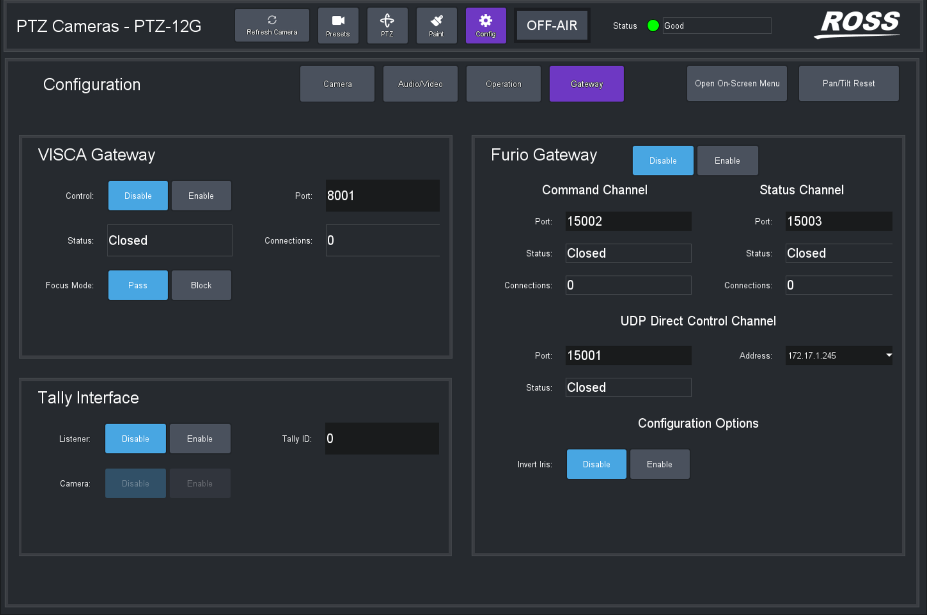
Figure 17 - Gateway Settings page
VISCA Gateway
VISCA Gateway settings (Figure ??) enable you to open a server port to connect VISCA controllers, such as a Carbonite switcher, to the camera via the camera control panel.
The communication protocol is serial VISCA over TCP. Only a subset of VISCA commands is supported. This VISCA gateway implementation is not compatible with the legacy PIVOTCam Control Panel.
In the PTZ Camera Control plugin , you can configure whether the numbering of presets starts at 0 or 1 . The setting is purely aesthetic, and can be changed at any time. For many external VISCA controllers, such as Carbonite, preset numbering starts at 1 . If such a VISCA controller recalls preset 1 , the first preset is recalled, regardless of whether the PTZ Camera Control plugin shows it as preset 0 or 1 . To avoid confusion, when using an external VISCA controller we recommend you set Preset Number Display Offset to match the controller’s numbering. For more information, see “Preset Number Display Offset”, which is within the section, “Operation Settings Page”.
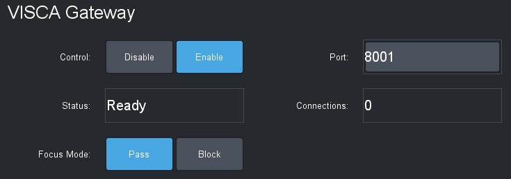
Figure 18 - VISCA G ateway settings
VISCA Gateway settings include the following:
-
Control — To open a server port, set Control to Enable .
-
Port — The port number. Can be edited only when Control is set to Disable .
-
Status (read-only):
- Closed — The port is closed, either because the gateway is disabled or because DashBoard is not connected to the target camera.
- Ready — The port is open, but no controllers are currently connected to it.
- Connected — The port is open and one or more controllers are connected to it.
- Error — Typically means that the selected port is unavailable. For example, it may be in use by a different service or as a gateway for a different camera.
-
Connections (read-only) — When status is Connected , shows how many connections are established.
-
Focus Mode :
- Pass — External controllers are allowed to send focus mode control messages through the gateway.
- Block — Prevents focus mode control messages from being passed through the gateway to the camera. External controller can still read the current state of camera auto focus mode from the camera control panel. This is done because Carbonite always pushes its desired auto focus mode, which means that when Carbonite is connected, no other controller can set auto focus.
If a VISCA controller triggers a preset store in an empty DashBoard slot, the preset is given the name "Remote", and default store options are applied. If a preset is stored to a location that already has name and preset options set, that name and preset options are retained and the preset is updated with the current camera position.
Furio Gateway
Furio Gateway settings (Figure ??) enable you to open server ports to allow external devices to control the camera using Furio API commands. You can control the camera using SmartShell, an Acuity production switcher, or another device that sends Furio API commands.
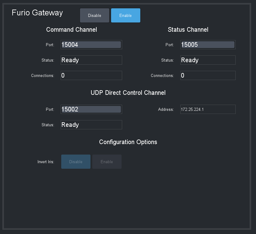
Figure 19 - Furio Gateway settings
Both the DashBoard computer running the PTZ Camera Control Plugin, and the external Furio control device must be properly configured to establish control of the camera.
The Command Channel and Status Channel are ports on the DashBoard computer that must be opened to enable an external Furio control device to communicate with the PTZ cameras.
The UDP Direct Control Channel consists of a Port and IP Address on the DashBoard computer. The Furio Joystick Panel must be able to access the port and IP address.
The Status box for each channel may display any of the following messages:
-
Closed — The port is closed, either because the gateway is disabled or because DashBoard is not connected to the target camera.
-
Ready — The port is open, but no controllers are currently connected to it.
-
Connected — The port is open and one or more controllers are connected to it.
-
Error — Typically means that the selected port is unavailable. For example, it may be in use by a different service or as a gateway for a different camera.
When the gateway is enabled, the Connections box in the Command Channel area and in the Status Channel area display the number of established connections.
The Configuration Options to Invert Iris is available for all PTZ cameras. When enabled, iris velocity changes requested through Furio Gateway are inverted. To revert to Dashboard v9.15 or earlier version behavior, Enable the Invert Iris option.
Port numbers and IP addresses for the Furio Gateway can be configured only while the gateway is Disabled .
Reporting of Movement Away from Preset Position
When controlling a PTZ camera through the Furio Gateway, the gateway reports when the camera has moved away from a preset position. In SmartShell this would have the effect of changing the border around the last recalled preset from dark blue to light blue. Motion is reported only for pan, tilt, zoom and focus axes changed by a controller connected to the DashBoard plugin hosting the gateway, such as when one of the following occurs:
- Movement is requested by the PTZ Camera Control plugin, either by using PTZ controls in the plugin interface, or by using a USB game controller.
- Movement is requested by a controller connected to the VISCA or Furio Gateway hosted by the DashBoard plugin (for example a SmartShell joystick or Carbonite).
Reporting of Variable Zoom Settings
For cameras that feature a Variable Zoom setting, the variable zoom value is reflected through the Furio gateway when it reports the zoomVar setting for the Pan and Tilt axes:
-
When Variable Zoom is OFF , zoomVar for Pan and Tilt is reported as 0 .
-
When Variable Zoom is ON , zoomVar for Pan and Tilt is reported as 100 .
-
When Variable Zoom is not available, or for all other axes (Zoom, Focus, Iris), zoomVar is reported as 50 .
In all cases, zoomVar cannot be changed through the Furio Gateway.
Tally Interface
Settings in the Tally Interface area (Figure ??) enable listeners to receive tally signals, assign a tally ID for the camera, and specify control of the tally indicator on the camera.
The top of the PTZ Camera Control interface features a tally indicator (ON-AIR / PREVIEW / OFF-AIR).
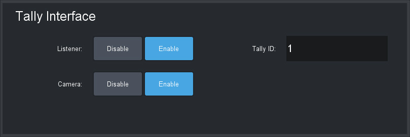
Figure 20 - Tally Interface settings
Settings in the Tally Interface work in conjunction with the DashBoard Tally Service . You must enable the DashBoard Tally Service and then configure tally settings for your camera.
To enable the DashBoard Tally Service:
-
From the DashBoard Tree, expand DashBoard Services and the double-tap Tally .
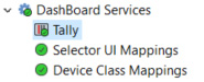
Figure 21 - DashBoard Tree, showing DashBoard Services > Tally
-
The DashBoard Tally Service interface appears (Figure ??).
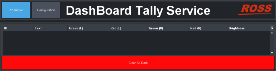
Figure 22 - DashBoard Tally Service interface
-
Tap the Configuration button, and then turn ON the tally listener type used in your facility (Figure ??).
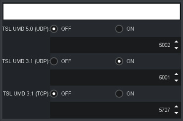
Figure 23 - Specifying a T ally Listener
-
Tip : To observe incoming tally data, tap the Production button.
To configure tally settings for your camera:
-
In the PTZ Camera Control interface, navigate to Config > Gateway .
-
In the Tally Interface area, specify tally settings for the camera:
-
Set Listener to Enable .
Enabling a listener activates the tally indicator (ON-AIR / PREVIEW / OFF-AIR ) at the top of the PTZ Camera Control interface. Whenever the tally state changes, the tally indicator responds accordingly. Notification of each state change is also delivered to SmartShell over the Furio Gateway (if configured).
-
In the Tally ID box, type the tally number for the camera.
-
If you want DashBoard to control the camera’s tally light, set Camera to Enable :
-
For PTZ-12G+, PTZ-12G, and PTZ-NDI cameras, PIVOTCam cameras, and Lumens PTZ cameras, the tally light is red when the camera is ON-AIR , and green when the camera is in PREVIEW .
-
For Sony BRC cameras, there is a red tally light on the camera, which is illuminated when the camera is ON-AIR .
-
For Sony ILME-FRZ cameras, there are green and red tally lights, which are illuminated when the camera is ON-AIR .
-
For Panasonic and Canon PTZ cameras, there are separate tally lights for ON-AIR (red) and PREVIEW (green).
noteIf you enable control of the camera tally light, the ability to directly control the tally light through the VISCA gateway or from a DashBoard CustomPanel is disabled.
-
-
On-Screen Menu
The on-screen menu, controlled through the Menu Control page, enables you to adjust camera settings without using the remote control unit that came with the camera. For information about which settings are available in the on-screen menu, consult the User Manual that came with your camera.
To access the on-screen menu:
-
Tap the Open On-Screen Menu button.

The Menu Control interface appears (Figure ??).
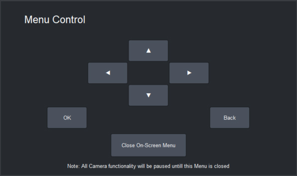
Figure 24 - Menu Control interface
To adjust settings in the on-screen menu:
- Connect video output from the camera to a video monitor so you can see the menu options.
- Tap the up/down and left/right arrows to navigate to the desired setting, and then tap OK button to select it.
The on-screen menu is not available for Canon PTZ cameras.
Tips:
- If you want to go up one level in the menu hierarchy, tap the Back button.
- After a period of inactivity (15 seconds for PTZ-12G+, PTZ-12G, and PTZ-NDI cameras), the on-screen menu closes automatically. You must close and re-open the Menu Control page to continue using the on-screen menu.
- While the on-screen menu is active, all other camera activity is paused.
- The Sony ILME-FR7 menu supports press-and-hold on the on-screen menu buttons.