Aux Power Module
The Auxiliary Power Module is installed in the same slots as the tally ports at the back of the control panel and reduces the maximum number of tallies you can have from the control panel.
To Instal the Aux Power Module
You must disconnect and remove the existing tally board in the first slot and install the new aux power module and cable it up.
| Warning Hazardous Voltages: Hazardous voltages are present in this device as long as any of the power supplies are connected to the AC power. |
| ESD Susceptibility: Static discharge can cause serious damage to sensitive semiconductor devices. Avoid handling the switcher circuit boards in high static environments such as carpeted areas and when synthetic fiber clothing is worn. Touch the frame to dissipate static charge before removing boards from the frame and exercise proper grounding precautions when working on circuit boards. |
- Power down the control panel and disconnect the AC power.
-
Remove all the power and control cables from the first Tally board. The Aux Power modules must be installed into the first slot in the panel
and the existing Tally board moved to an another slot.

- Locate an empty slot for the Tally board you are moving and remove the four (4) screws from the blank plate and remove it from the slot.
-
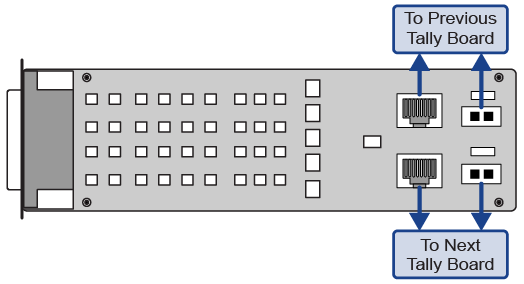
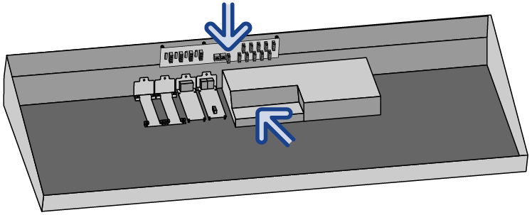
Align the Tally board with the ports out the hole in the back of the tub and the four (4) screw holes with the standoffs on the bottom of the
tub. Install the screws.

-
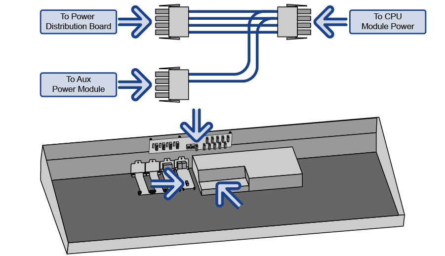
Replace the existing 2-pin power cable connected to the Control Panel CPU module with the longer cable (4820CR-322) that
came in the kit.

-
Reconnect the RJ45 cables and remaining 2-pin power cables to the Tally boards.
Note: You will have to swap all of your tally connectors to match the new numbering of the boards.
-
Align the Aux Power module with the ports out the hole in the back of the tub and the four (4) screw holes with the standoffs on the bottom of
the tub. Install the screws.

-
Remove the 4-pin power cable connecting the Control Panel CPU module to the Power Distribution board.

-
Connect the new 4-pin power cable (4820CR-322-02) that came in the kit in place of the old power cable you just removed. The 2-conductor lead
connects to the Aux Power module.

-
Connect equipment to the Auxiliary Power ports as required using the provided cables.
CAUTION: Only use the cables provided to connect your Acuity Auxiliary Control Panel or Touchscreen display to the Auxiliary Power module.Tip: The status LEDs indicate whether each port is ok (green), or if there is a fault (red).

