SideBox Installation and Setup
The SideBox enclosure can be used with both the Acuity™ and Carbonite switchers. The SideBoxNet enclosure is only supported by the Acuity™ switcher running software version 6.0 or higher.
The SideBoxNet enclosure comes pre-assembled with a number of modules and includes the SideShotNet, SideSlideNet, and SideStick. All of these product are installed and connected to the switcher in the same way, and only differ in setting up the actual module itself.
Installation
SideBox and SideBoxNet can be installed onto a desk, into the desk using the supplied mounting brackets, or onto a standard VESA mount.
Desk Mounting
The enclosure can be mounted into a desk in either a flat or sloped position. How you want the enclosure to be positioned determines where the mount brackets are installed.
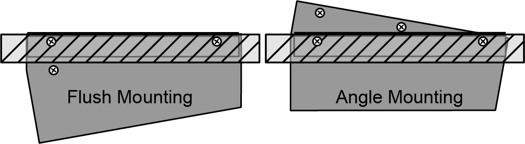
If you are sitting the enclosure onto a desk you do not need to install the mounting brackets.
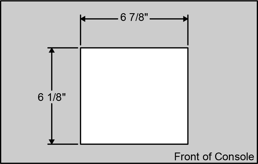
Desk Cutout
The desk cutout size for the enclosure is the same if you are mounting it in the flat or sloped position.
To Install the In-Desk Mounting Brackets
-
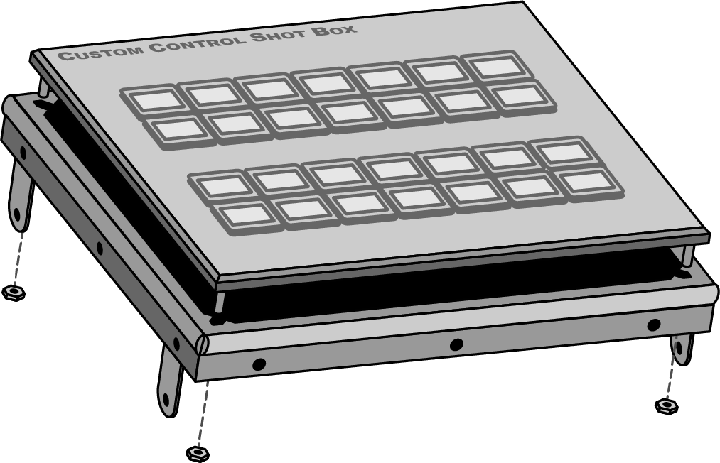
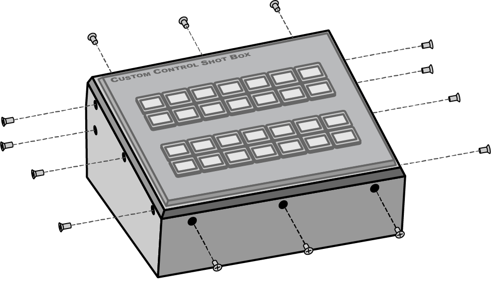
Remove the mounting screws from the side of the enclosure for the mounting option you have chosen.
Figure 3. Mounting Screws 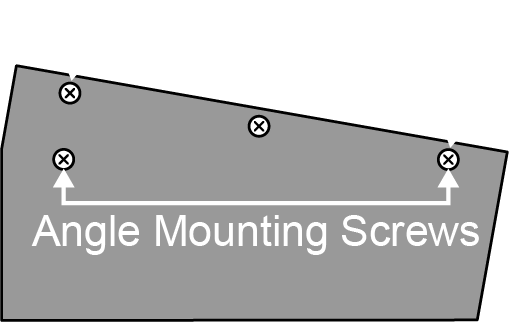
-
Install the mounting bracket onto the side of the enclosure using the screws you just removed.
Figure 4. Mounting Bracket 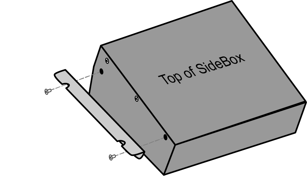
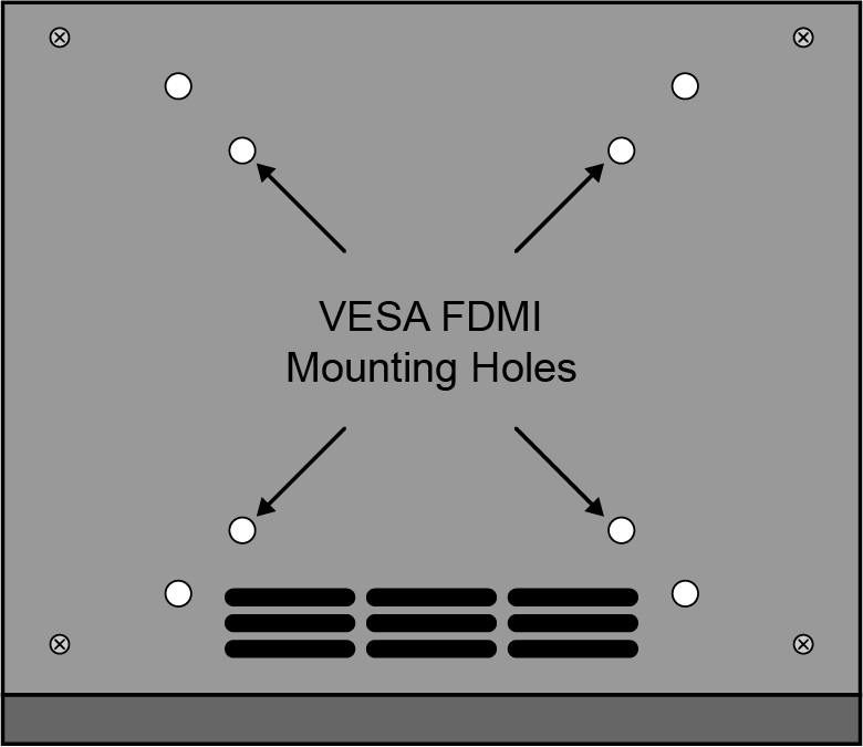
VESA® Mounting
The enclosure can be mounted onto a VESA® FDMI MIS-D 75 or 50, C Mounting Arm.
Cabling
Depending on whether you have a SideBox or SideBoxNet, the cabling of your enclosure will be different.
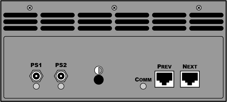
SideBox Cabling
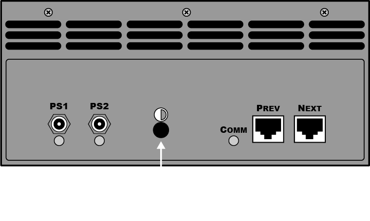
Each SideBox enclosure has connectors for primary (PS1), and secondary (PS2) power supply, and two RJ-45 communications ports (PREV and NEXT).
To Cable SideBox with Acuity™
- Connect and secure one end of the Control Cable to the External Link port 2, 3, or 4 or another external module already connected to the control panel.
- Connect and secure the other end of the Control Cable to the PREV port on the SideBox.
- Connect and secure one 12V DC Power Supply to the PS1 connector on the back of the SideBox.
To Cable SideBox with Carbonite
Carbonite and Carbonite Black can only support a single SideBox at a time.
SideBoxNet Cabling
The SideBoxNet connects to the switcher over a standard ethernet connection.
.png)
SideBox Setup
Acuity™ must be set up to communicate with the SideBox. Carbonite and Carbonite Black automatically recognise and will communicate with the SideBox.
To Set Up Communication to a SideBox Module
The SideBox must be set up on an external link on the Acuity® control panel.
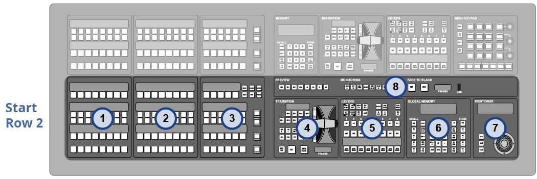
To Manually Map Modules to a Row
Modules are mapped to rows so that the system can identify where the hardware is located on the panel.
To Automatically Map Modules to a Row
Modules are mapped to rows so that the system can identify where the hardware is located on the panel.
-
Press a button on all the modules that you want to assign to the selected row starting with the first source button/crosspoint module on the left. Remember to include memory and
transition modules as well.
The order that source button modules are assigned to a row sets the order that the switcher maps to the buttons.
Note:The Flex Control modules on the TouchDrive panels must be mapped manually.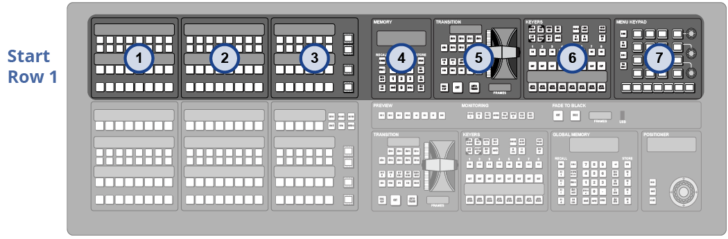
-
Repeat for each additional row you want to assign modules to.
LCD Contrast
If the module installed in the SideBox has an LCD display, such as mnemonics, the contrast of this display must be adjusted manually using a Phillips screwdriver.
SideBoxNet Setup
The SideBoxNet connects to the switcher over ethernet. DashBoard is used to configure the network settings on the SideBoxNet as well as monitor status and perform upgrades.
SideBoxNet Network Settings
By default, the SideBoxNet uses DHCP to automatically obtain an IP address. You can manually set a static IP address, network mask, and default gateway if your network does not have a DHCP server or if you need to set a static IP.
The enclosure is automatically discovered in DashBoard and appears as Panel followed by the MAC address of that particular SideBoxNet.
To Configure the Network Setting
You can use DashBoard to set the network settings of the SideBoxNet.
To Assign a Custom Name
The name appears in the tree view in DashBoard and allows you to easily identify your particular device.
- Double-click on the Panel node and click on the Panel Name, Permissions tab.
- In the Panel Name field, enter the new name.
Additional Settings
Additional settings allows you to set alarms for power supply failures, permissions to change settings in DashBoard, or to restore default settings.
To Edit Permissions
You can lock the settings to prevent other users from changing them.
- Double-click on the Panel node and click on the Panel Name, Permissions tab.
- On the Edit Permission list, click Unlocked to allow all the parameters to be set, or Locked to lock all parameters except this one.
To Set an Alarm
The alarm notifies users in DashBoard that a power supply is failing.
- Double-click on the Panel node and click on the Alarm Enables tab.
-
Select the alarms that you want to enable.
- PSU1 Voltage Out of Range — alarm if power supply 1 is out of the safe acceptable voltage range
- PSU2 Voltage Out of Range — alarm if power supply 2 is out of the safe acceptable voltage range
To Restore Default Settings
All settings, except for the network settings, can be defaulted back to the factory settings.
DIP Switches
The up position for the DIP switch is OFF.
| DIP1 | DIP2 | DIP3 | DIP4 | Function |
|---|---|---|---|---|
| OFF | OFF | User IP Settings | ||
| OFF | ON | Force DHCP IP | ||
| ON | OFF | Force Static IP (192.168.2.10) | ||
| ON | ON | Force Static IP (10.1.2.10) | ||
| OFF | You must enter your DashBoard password to save changes to this module in DashBoard. | |||
| ON | No password is required. | |||
| OFF | Default Boot | |||
| ON | Boot from memory card |
Restart and Status LED
Press and hold the RESET button to restart the unit. The Status LED changes colors to indicate the status.
- Off — no power connected
- Red — Booting
- Blinking — Upgrading
- Green — Normal
Setting Up Communications with Acuity™
To use SideBoxNet with Acuity™ you must set up communications between the two. Once communications are set up you can configure the particular module that you have installed in the SideBoxNet.
To Set Up Communication to a SideBoxNet Module
You can connect up to 15 unique SideBoxNet enclosures to a switcher. The number of each SideSlideNet, SideShotNet, and SideStick modules depends on the type of module you are connecting.
Replacing a SideBox Module
To Remove a Module
-
Remove the 14 screws from the front, back, and sides of the SideBox.
-
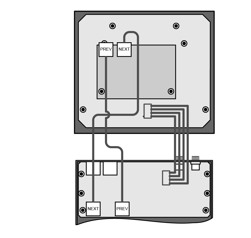
Disconnect both of the module control link cables and the power cable from the module.
-
Remove the 4 retaining nuts that secure the module onto the module mounting plate.