Web Interface
You can connect to PTZ-12G+ over an IP network to configure them and to view live video.
This section describes how to connect to a camera, and describes the camera’s built-in web interface. It also provides information about viewing an RTSP video stream.
Topics include the following:
Connecting to the Web Interface
You can connect to a camera via a network switch or router, or by connecting a network cable directly from the camera to your computer.
Network cable type must be CAT6 (minimum).
To connect via a network switch or router:
- Connect a network cable between the camera and the network switch or router (Figure ??).
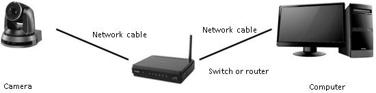
Figure 1 - Connecting over an IP Network
To connect directly, using a network cable:
-
Connect a network cable between the camera and your computer.
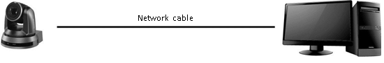
Figure 2 - Connecting Directly using a Network Cable
-
Configure the IP address , Subnet mas k , and Default gateway on your computer so it is on the same network segment as the camera (Figure ??).
tipThe camera’s factory-set default IP address is 192.168.100.100 . Each device on the network must have a unique IP address.
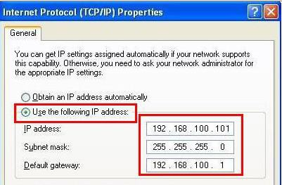
Figure 3 - Configuring the IP Address, Subnet mask, and Default gateway
To Access the Web Interface:
-
In a web browser, navigate to the IP address of the camera.
tipThe factory-set default IP address is 192.168.100.100 . Each device on the network must have a unique IP address.
The login window appears.
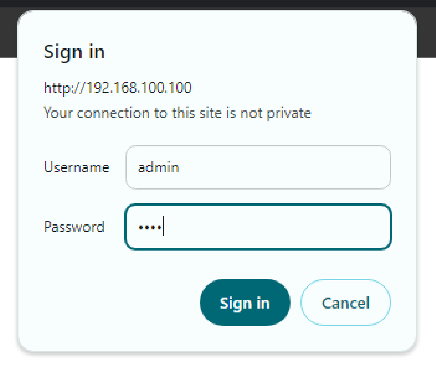
Figure 4 - Login Window
-
Type a valid Username and Password , and then click the Login button.
tipThe default User n ame is admin . The default Password is 9999 . If this is the first login, you are prompted to change the password.
The web interface appears (Figure ??).
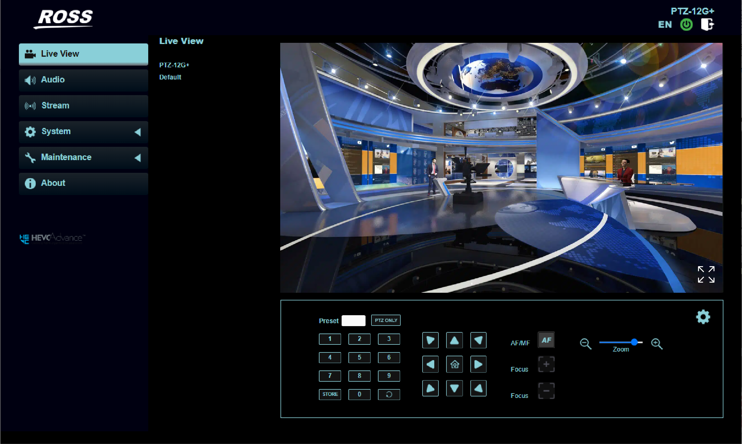
Figure 5 - Web Interface for a PTZ-12G + Camera
-
Note : Live video in the web interface is available only with NDI|HX disabled. For NDI|HX, you can use the NDI® Studio Monitor tool, which is part of a free NDI Tools package available through https://ndi.tv/tools.
Web Interface Features
This section describes the web interface for PTZ-12G+
It includes the following topics:
- “Login Window”
- “Live View Page”
- “Settings: Camera Page”
- “Audio Settings Page”
- “Stream Page”
- “System: Device”
- “System: Output”
- “System: Network”
- “System: Security”
- “System: Date & Time”
- “System: User”
- “System: Control”
- “Maintenance Page”
- “Maintenance: Reboot”
- “About Page”
L ogin Window
This section describes features available on the Login window (Figure ??).
Figure 6
Figure 25 - Login Window
Table 1
| No. | Item | Function Descriptions |
|---|---|---|
| 1 | Username | Enter username (default: admin) |
| 2 | Password | Enter user password (default: 9999) If this is the first login, you are prompted to change the password, and the Edit Users page appears. For more information, see “System: User”. |
| 5 | Sign In button | Logs in to the web interface. |
Live View Page
This section describes features available on the Live View page (Figure ??).
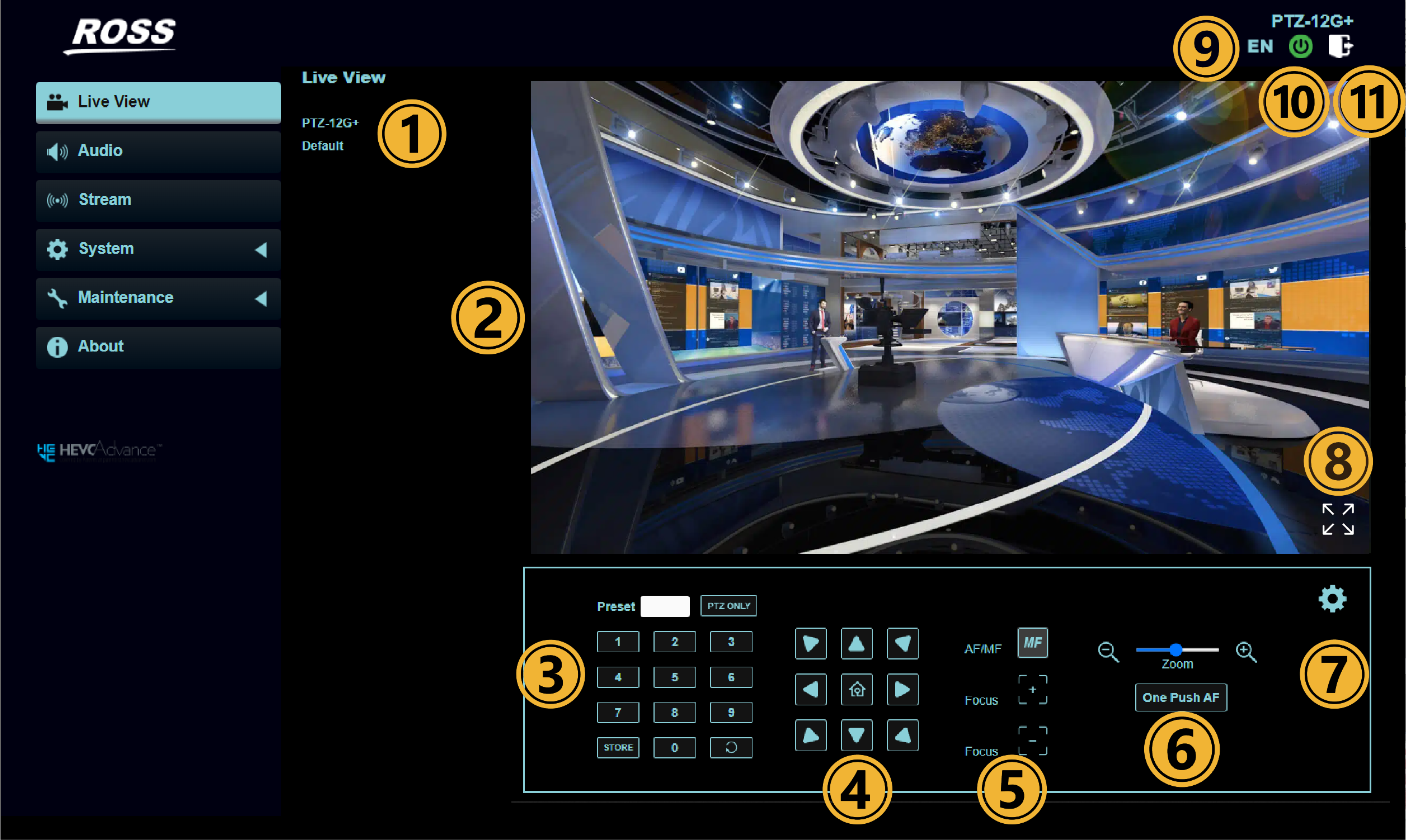
Figure 7 - Live View Page
Table 2
| No | Item | Function Descriptions |
|---|---|---|
| 1 | Camera ID/ location | Displays the camera ID location, which can be customized. |
| 2 | Preview window | Shows live video from the camera. Note: Not available when NDI|HX2 or NDI|HX3 are enabled. |
| 3 | Preset setting | Type or select a preset number, and then do one of the following:
|
| 4 | Pan / Tilt setting | Adjust the Pan/Tilt position of the camera. |
| 5 | Auto/Manual Focus | Switch to Auto /Manual Focus and adjust Focus in Manual Focus mode. Note: Use the +/- buttons to manually focus. |
| 6 | Zoom | Adjusts the zoom position of the camera lens. |
| One Push AF | When Manual Focus Mode is On, select to perform one Auto Focus. | |
| 7 | Camera Setting | Refer to “Settings: Camera Page” for relevant settings |
| 8 | Switch to Full Screen | Switches the preview window to full screen. Note: Not available when NDI|HX2 or NDI|HX3 are enabled. |
| 9 | Language | Supports English/Traditional Chinese/Simplified Chinese |
| 10 | Power button | Turns camera power On or places it in Standby mode. |
| 11 | Logout | Log out of the web UI. |
Settings: Camera Page
This section describes features available on the Settings > Camera page (Figure ??).
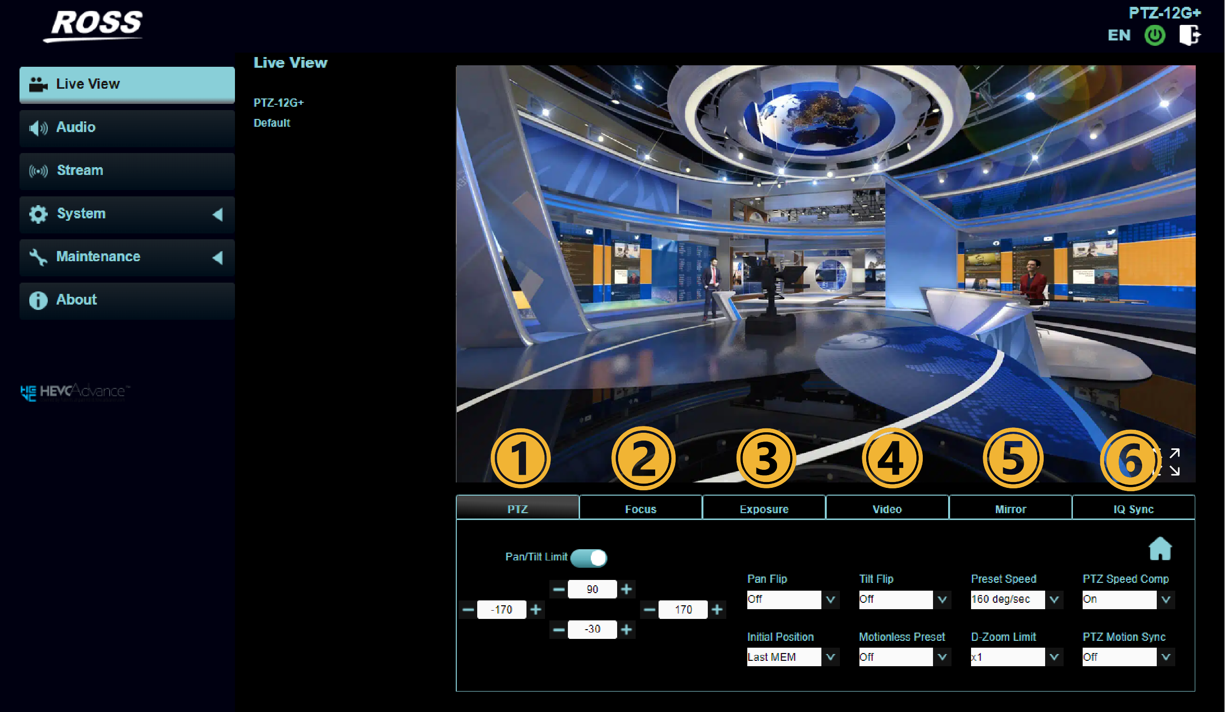
Figure 8 - Settings > Camera Page
Table 3
| No | Item | Function |
|---|---|---|
| 1 | PTZ | 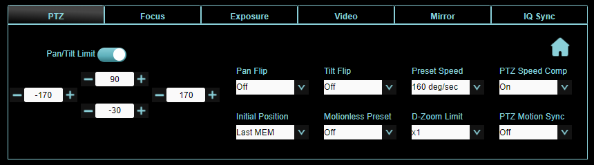
|
| 2 | Focus | 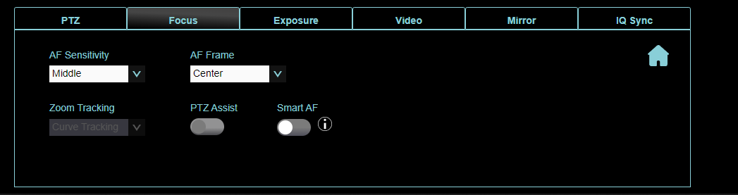
|
| 3 | Exposure | 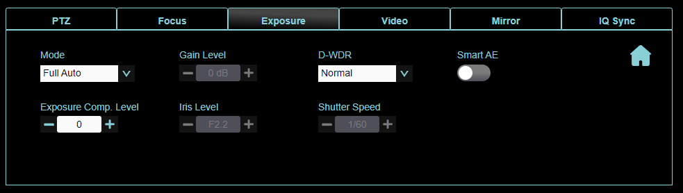
|
| Video | 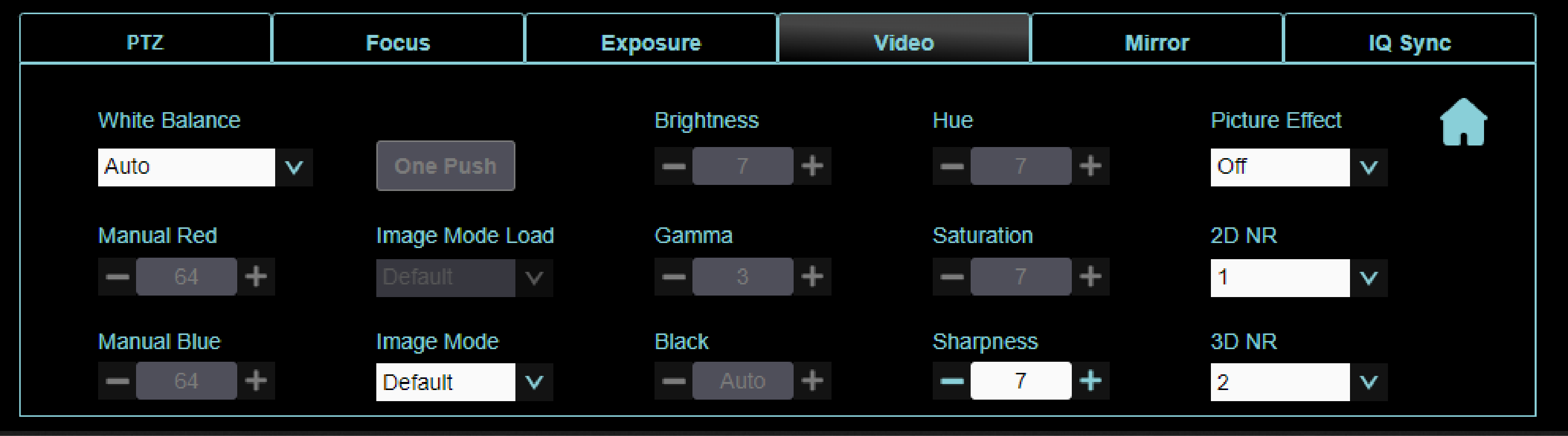
| |
| 5 | Mirror | 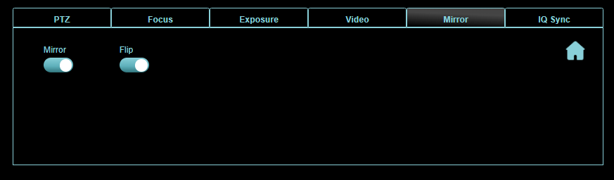
|
| IQ Sync | 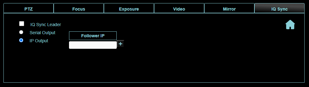
|
Audio Settings Page
This section describes features available on the Audio page (Figure ??).
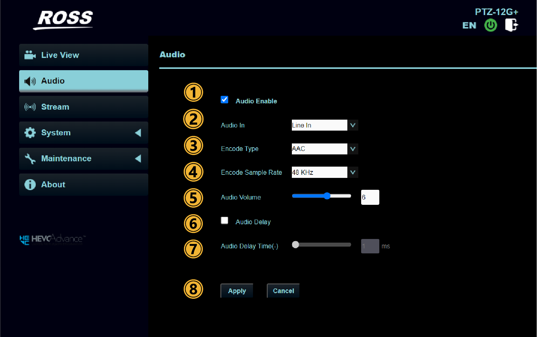
Figure 9 - Audio Page
Table 4
| No | Item | Function Descriptions | ||||||||
|---|---|---|---|---|---|---|---|---|---|---|
| 1 | Audio Enable | Enables or disables the Audio Input port on the camera. | ||||||||
| 2 | Audio Input setting type | Sets MIC In/Line In | ||||||||
| 3 | Encode Type | AAC / G.711 Available with NDI|HX disabled. | ||||||||
| 4 | Encode sample rate | Set Encode sample rate
Available with NDI|HX disabled. | ||||||||
| Audio Encode | IP Stream | HDMI Full NDI | SDI | USB 3.0 | ||||||
| RTSP | RTMP/RTMPS | MPEG-TS | SRT | |||||||
| 48 KHz(AAC) | Yes | Yes | Yes | Yes | Yes | Yes | Yes | |||
| 44.1 KHz(AAC) | Yes | Yes | Yes | Yes | Yes | No | Yes | |||
| 16 KHz(AAC) | Yes | No | Yes | Yes | No | No | Yes | |||
| 16 KHz(G.711) | Yes | No | No | No | No | No | No | |||
| 8 KHz(G.711) | Yes | No | No | No | No | No | No | |||
| 5 | Audio Volume | Adjusts Volume | ||||||||
| 6 | Audio Delay | Turns on / off Audio Delay. Available with NDI|HX disabled. | ||||||||
| 7 | Audio Delay Time (ms) | Set Audio Delay Time (-1~-500ms) Available with NDI|HX disabled. | ||||||||
| 8 | Apply/ Cancel | Select Apply to save changes. | ||||||||
Stream Page
This section describes features available on the Stream page (Figure ??).
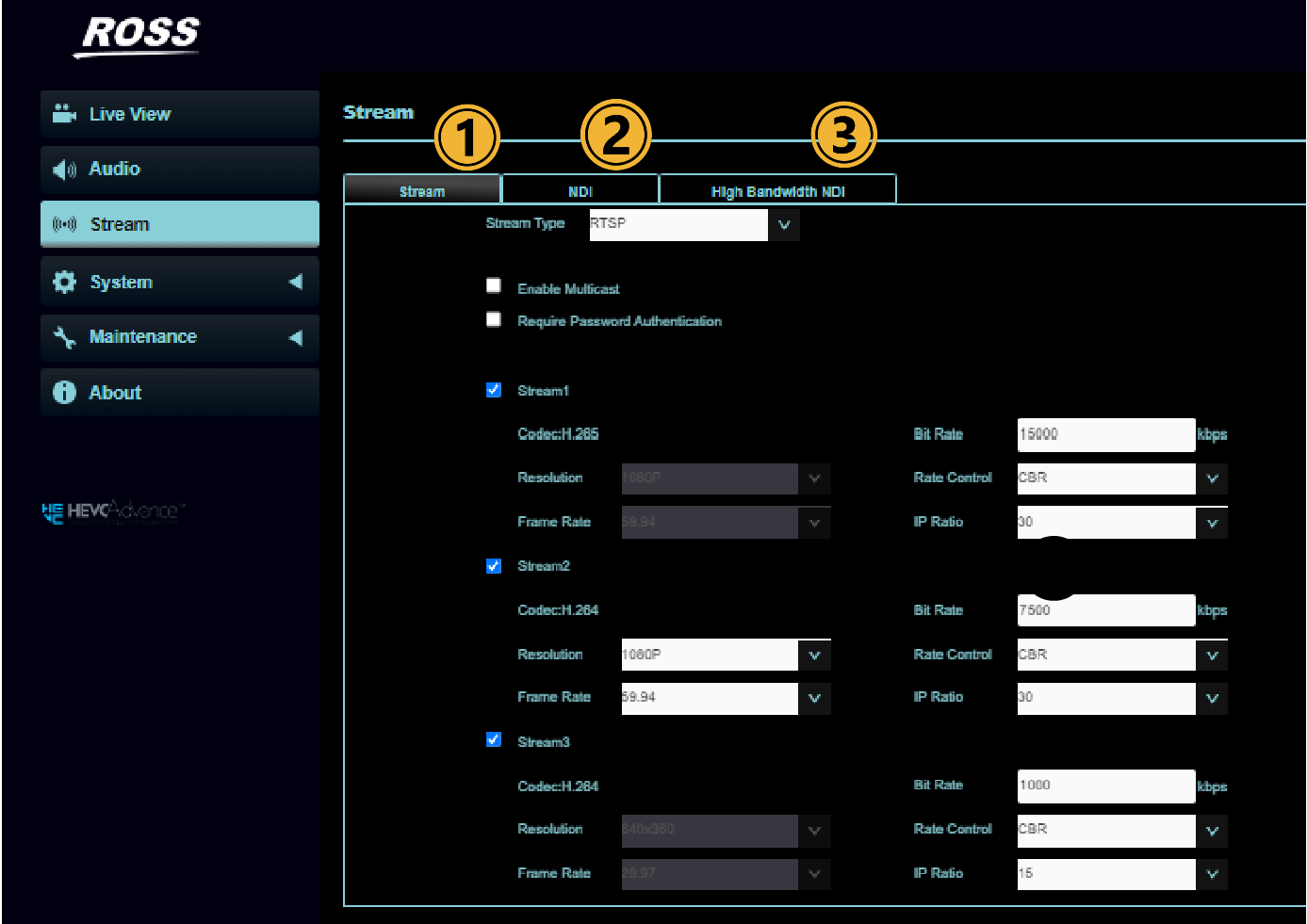
Figure 10 - Stream Page
There are 3 tabs within the stream page, they are:
-
Stream Tab
-
NDI Tab
-
High Bandwidth NDI Tab
Refer to the tables below for detailed overviews of each.
Stream Page > Stream Tab
Refer to the table below for the Stream tab options on the Stream page.
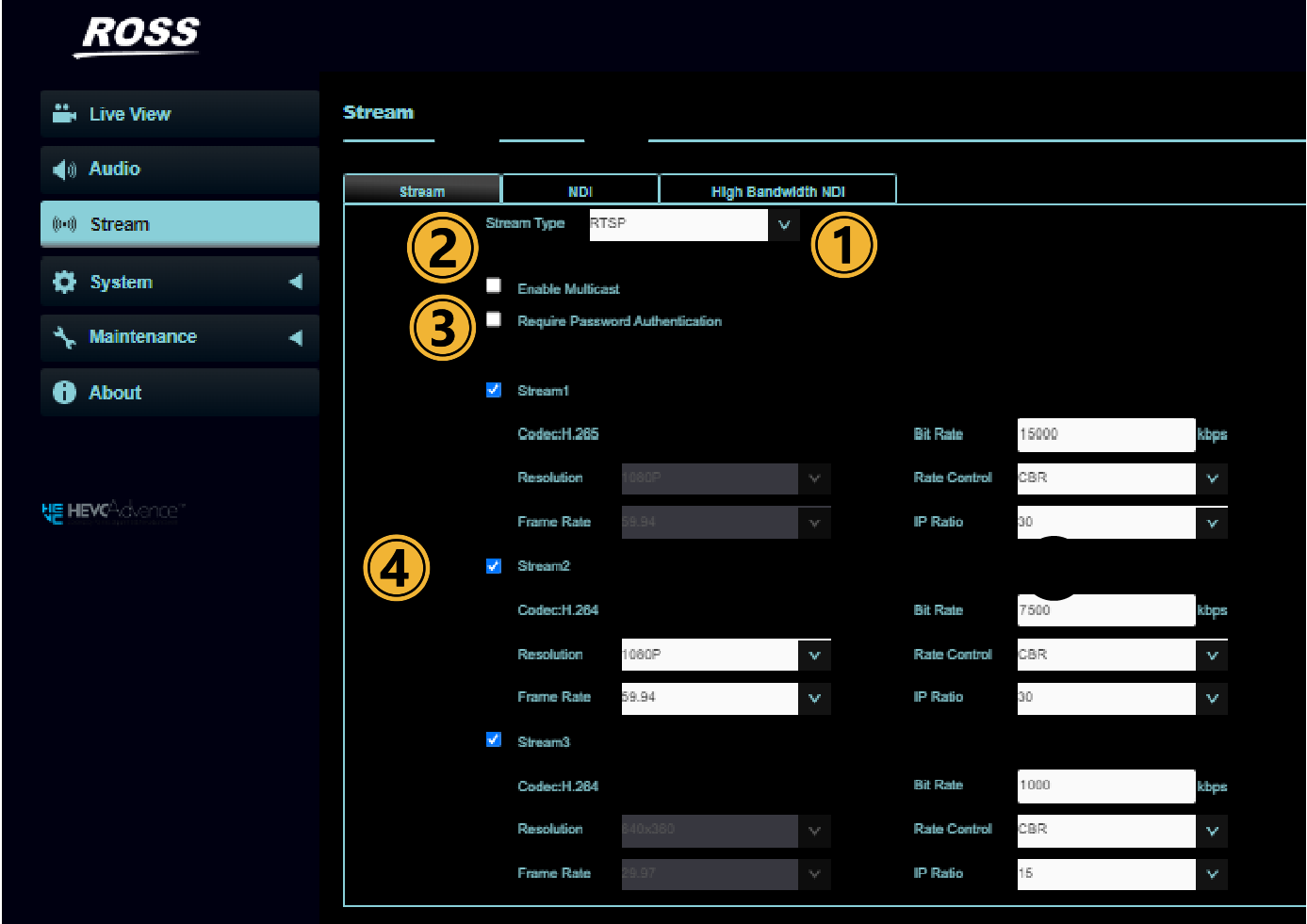
Figure 11 - Stream Tab
Table 5
| Tab | No | Item | Function Descriptions |
|---|---|---|---|
| 1 | Stream Type | Support types: MPEG-TS/RTMP/RTMPS/RTSP/SRT | |
| MPEG-TS Setting 1) Set MPEG-TS format. 2) Select Stream Source 1 or 2. 3) Enter the MPEG-TS IP address. 4) Enter port number, which must be set in the range above 1024 with a maximum value of 9999. IMPORTANT: Avoid using the following port numbers, as they are used by the camera: 3702, 5353, 8080, 9090, 8554, 8556, 8557, 52380, 52381. Available when the NDI|HX stream is disabled. MPEG-TS is supported only over UDP. | |||
| RTMP/RTMPS Setting Copy the RTMP web address provided by the RTMP service platform and paste it to the RTMP URL to publish the camera images on the RTMP service platform. You must also enter the Stream Key, and optionally select the Require Password Authentication check box to input an Account and Password. Tip: Before you can start live streaming to YouTube, audio must be enabled. For more information, see “Settings: Audio Settings Page”). Note: RTMP and RTMPS are available with NDI|HX disabled. | |||
| RTSP Setting Enable/Disable Multicast. It is suggested to enable Multicast when the number of users online watching the live image simultaneously is more than four. RTSP is available with NDI|HX disabled.
If password authentication is enabled use the following:
| |||
| SRT Setting 1) Set the field of SRT and then check the item to open SRT streaming. After the SRT streaming is opened, it will be connected automatically upon startup. 2) Select the Connection Mode as either Caller or Listener. 3) Enter the URL and port number, which must be set in the range above 1024 with a maximum value of 9999. IMPORTANT: Avoid using the following port numbers, as they are used by the camera: 8554, 8556, 8557, 8080. 4) Enter the Stream ID. 5) Delay time is for 20 to 8000 microseconds. The default value is 120 microseconds SRT is available when the NDI|HX stream is disabled. | |||
| 2 | Enable Multicast | Enable Multicast when more than 4 users online watch the image simultaneously. | |
| 3 | Require Password Authentication | If password authentication is enabled, the RTSP connection address is as follows:
| |
| 4 | Stream 1/2/3 Parameter Settings | Click a Stream tab to configure the associated RTSP video stream. Note: The Stream tabs are available only when Settings > Configuration > Output Source is set to HDMI + Streaming. Streams are available when NDI|HX is turned off. For information about settings on each Stream tab, see “Stream Page”. Stream 1 Functions Encode Format: H.265 Resolution: 4K Frame Rate: Setting according to the supported resolution Bit Rate (kbps): 2,000~20,000 Range, 15,000 Factory Default Rate Control: CBR/VBR IP Ratio: Setting according to the supported resolution Stream 2 Functions Encode Format: H.266 Resolution: 1080p/720p/1080i Frame Rate: Setting according to the supported resolution Bit Rate (kbps): 2,000~20,000 Range, 7,500 Factory Default Rate Control: CBR/VBR IP Ratio: Setting according to the supported resolution Stream 3 Functions Encode Format: H.266 Resolution: 640x360 Frame Rate: Setting according to the supported resolution Bit Rate (kbps): 512~5,000 Range, 1,000 Factory Default Rate Control: CBR/VBR IP Ratio: Setting according to the supported resolution | |
| 5 | Enable Stream | Enables / Disables the streaming channel. This setting is available with NDI|HX disabled. |
Stream Page > NDI Tab
Refer to the table below for the NDI tab options on the Stream page.
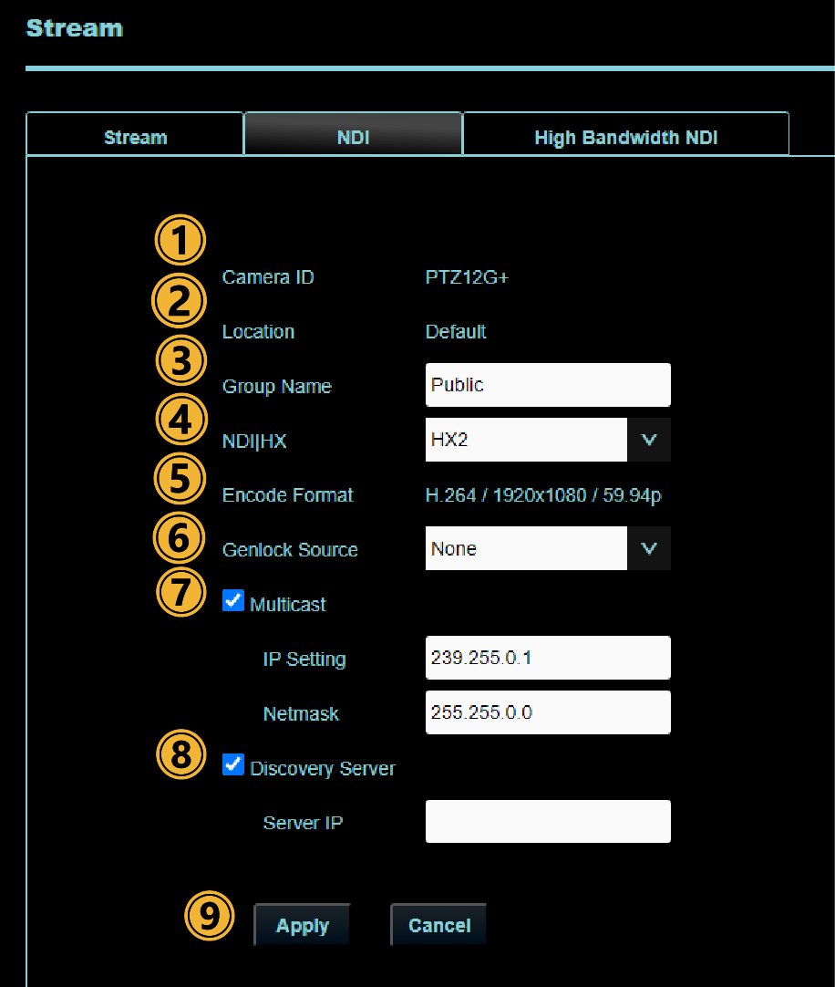
Figure 12 - Stream: NDI Tab
Table 6
| Tab | No | Item | Function Descriptions |
|---|---|---|---|
| 1 | Camera ID | The camera ID, which can be set in the System> Device page. | |
| 2 | Camera Location | The camera location, which can be set in the System > Device page. | |
| 3 | Group Name | The group name can be modified here and set with Access Manager - Receive in NDI Tool
Example: “default, 123, abc” means this machine belongs to three groups at the same time (default / 123 / abc) | |
| 4 | NDI|HX | Modify the NDI|HX connection by selecting HX2, HX3 or Off. Note: Enabling NDI|HX will disable Streamed video. Note: When NDI|HX is On, the Group Name text box appears. The default setting is Public, which leaves the stream exposed to anyone with access to the network. To set a unique group name, create the same group name in NDI Tools > NDI Access Manager. | |
| 5 | Encode Format | Encode format is reported here and is always H.264/Resolution/FrameRate. | |
| 6 | Genlock Source | NDI Genlock synchronizes multiple NDI sources (video streams) by creating a “genlock clock” attached to any NDI sender on the network. This ensures that all NDI streams are correctly timed with each other. | |
| 7 | Multicast | Enable Multicast when more than 4 users online watch the image simultaneously.
| |
| 8 | Discovery Server | Facilitates the automatic detection of the camera on the network.
| |
| 9 | Apply/Cancel | Select Apply to save changes. |
Stream Page > High Bandwidth NDI Tab
Refer to the table below for the High Bandwidth NDI tab options on the Stream page.
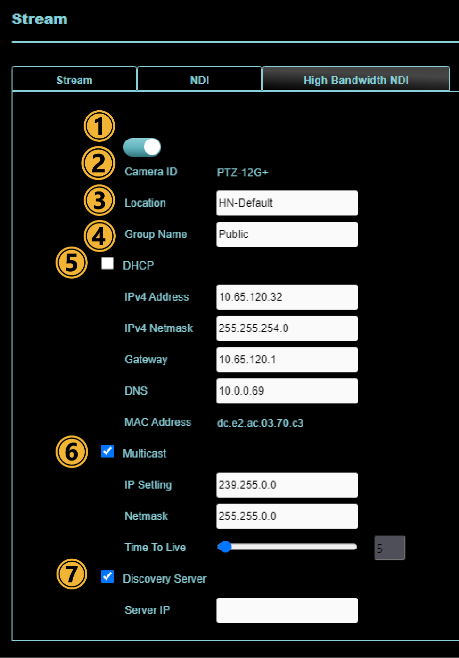
Figure 13 - Stream: High Bandwidth NDI Tab
Table 7
| Tab | No | Item | Function Descriptions |
|---|---|---|---|
| 1 | On/Off | Enable / Disable High Bandwidth NDI. | |
| 2 | Camera ID | Displays ID according to System Settings > Device settings. | |
| 3 | Location | A separate label to the Location set on the System > Device page, unique to the High bandwidth NDI. | |
| 4 | Group Name | Set the NDI group or groups for the NDI stream. To view the NDI stream, the group must also be added by Access Manager in the NDI Tools.
Example: “default, 123, abc” means this machine belongs to three groups at the same time (default / 123 / abc) | |
| 5 | DHCP | IP setting for High Bandwidth NDI. | |
| 6 | Multicast | Enable Multicast when more than 4 users online watch the image simultaneously.
| |
| 7 | Discovery Server | Check to enter the Server IP address |
System: Device
This section describes features available on the System: Device page (Figure ??).
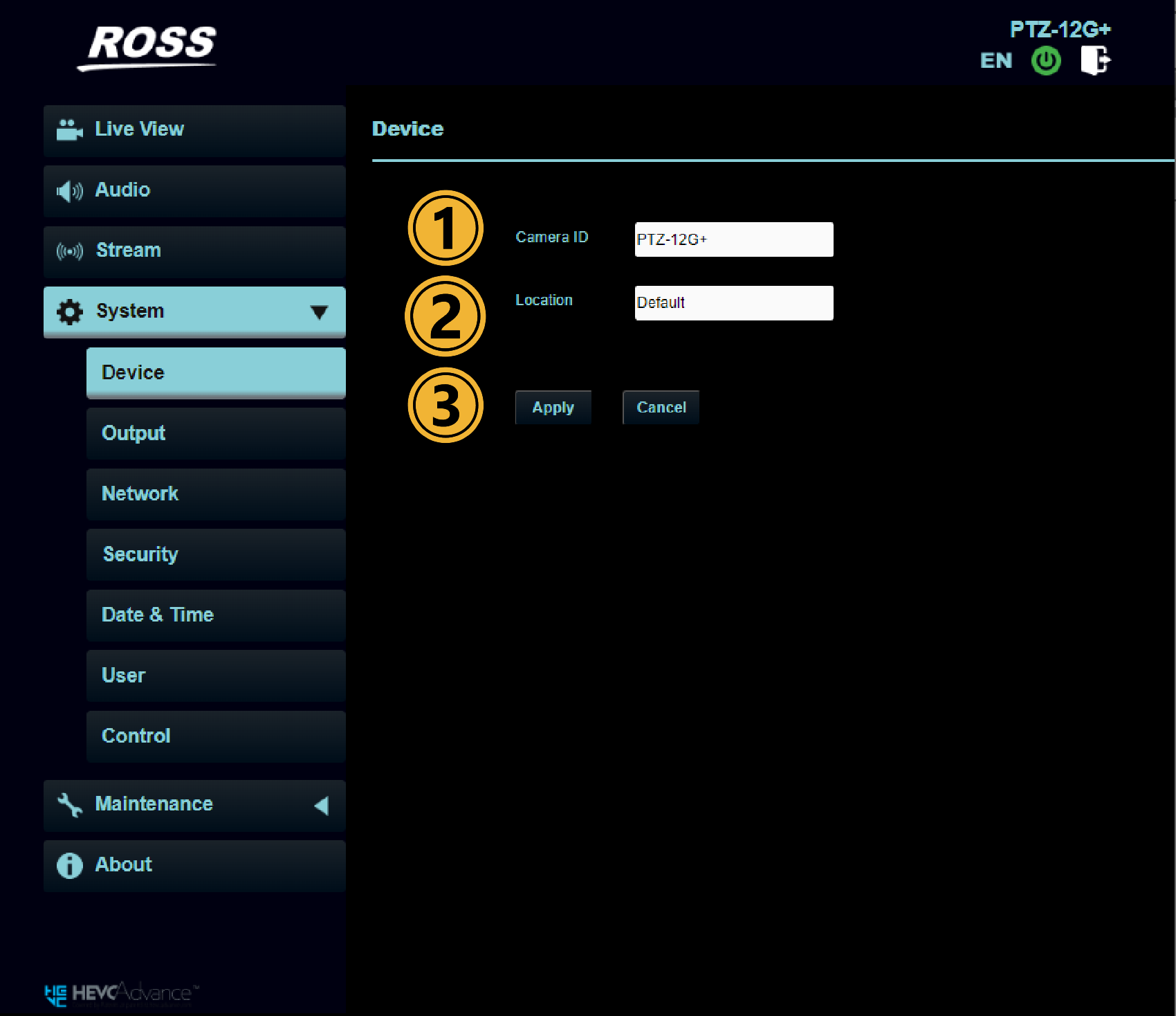
Figure 14 - System: Device Page
Table 8
| No | Item | Function Descriptions |
|---|---|---|
| 1 | Camera ID | Set the camera name • Camera names are limited to 1 - 12 characters • Characters are limited to uppercase and lowercase letters or numbers. Slashes (/), spaces, and special symbols are not allowed. |
| 2 | Location | Modify the location of the camera, such as Room 1 • Camera location is limited to 1 - 12 characters • Characters are limited to uppercase and lowercase letters or numbers. Slashes (/), spaces, and special symbols are not allowed. |
| 3 | Apply/Cancel | Select Apply to save changes. |
System: Output
This section describes features available on the System: Output page (Figure ??).
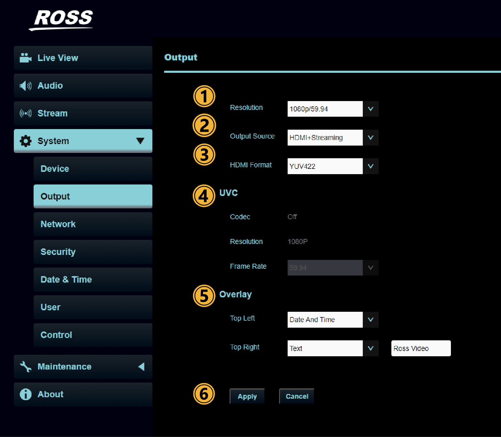
Figure 15 - System: Output Page
Table 9
| No | Function | Function Descriptions |
|---|---|---|
| 1 | Resolution | Set the resolution of the camera After switching the resolution, the camera will restart. Please refresh the browser |
| 2 | Output Source | Choices vary depending on whether NDI|HX is enabled in the Stream->NDI|HX page.
Setting output to HDMI + UVC will disable streaming and NDI|HX. UVC output only supports resolutions of 2160p/29.97 or lower. |
| 3 | HDMI Format | Select YUV422 / YUV420 / RGB YUV420 is only available for 2160p at 59.94 and 50 fps. |
| 4 | UVC | Note: The UVC tab is available only when Settings > Configuration > Output Source is set to HDMI + UVC. Encode (Codec) Format:
|
| 5 | Overlay | Set the stream to display “date and time” or “custom content” and to display location at two positions in the frame:
|
| Apply/Cancel | Select Apply to save changes. |
System: Network
This section describes features available on the System page (Figure ??).
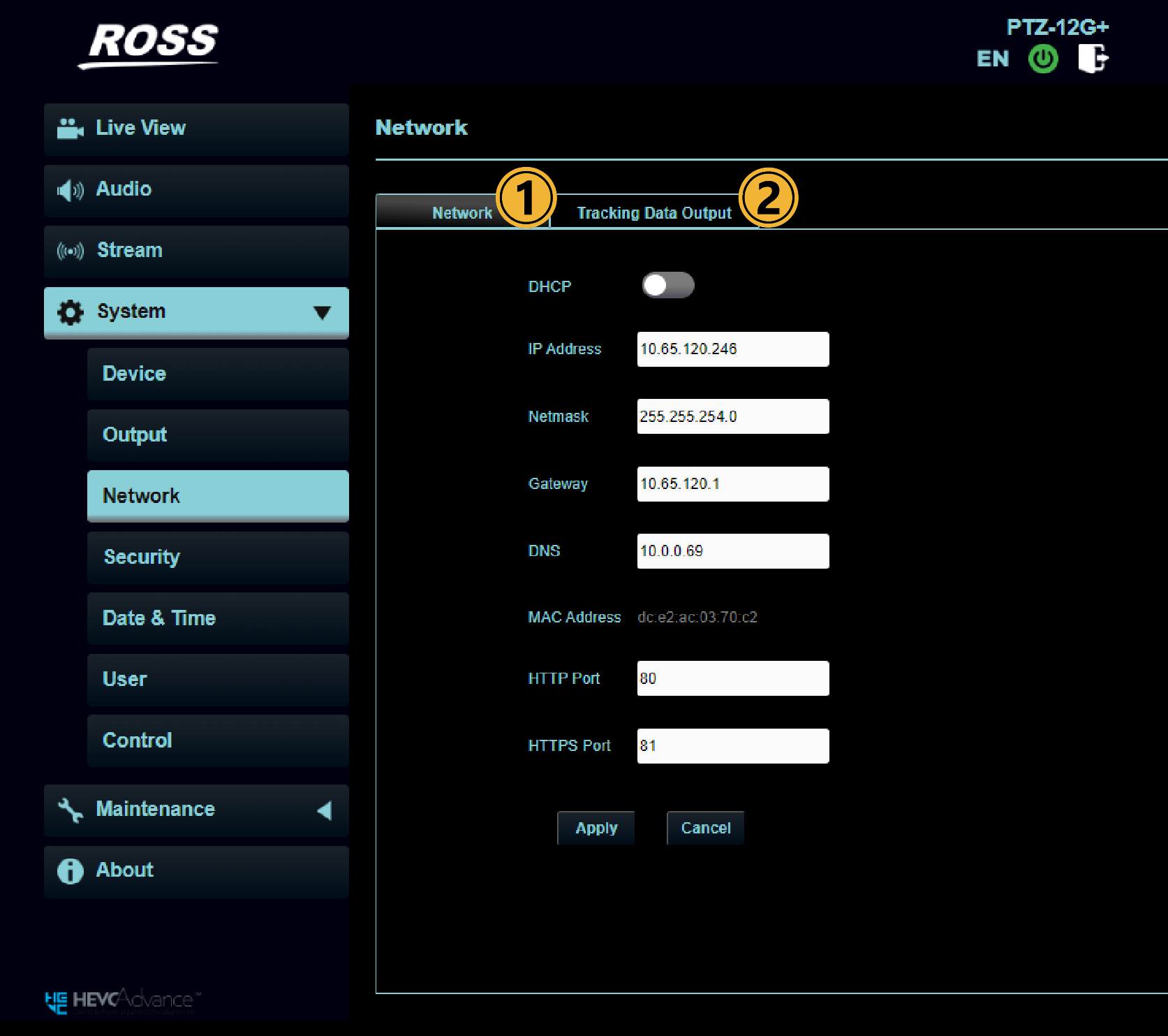
Figure 16 - System Page
Table 10
| Tab | No | Item | Function Descriptions |
|---|---|---|---|
| Network | 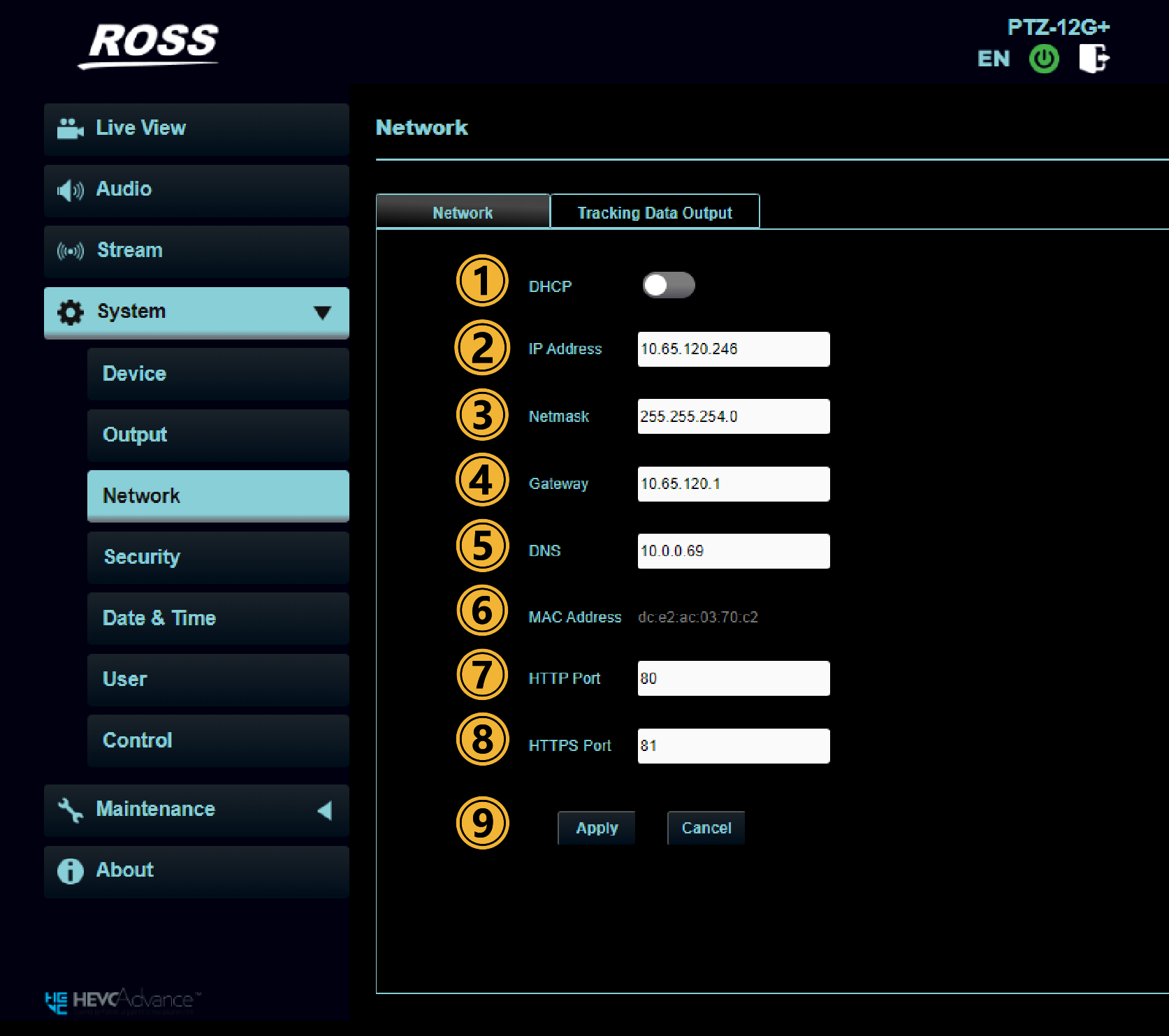 | ||
| 1 | DHCP | Dynamic Host Configuration Protocol. A network management protocol used to automatically assign IP addresses and other network configuration parameters (such as subnet mask, default gateway, DNS servers, etc.) to devices on a network. Change of setting is available when DHCP function is disabled. | |
| 2 | IP Address | IP Address for camera when DHCP is disabled. | |
| 3 | Netmask | Defines the range of IP addresses within the same network | |
| 4 | Gateway | Sets the Gateway of the camera. | |
| 5 | DNS | DNS — IP address of the DNS server | |
| 6 | MAC Address | A MAC (Media Access Control) address is a unique identifier assigned to network-connected devices. It consists of a 12-digit number in hexadecimal format. This identifier is embedded in your device's Network Interface Card (NIC) during manufacturing, ensuring each device on a network can be uniquely identified. | |
| 7 | HTTP Port | Set HTTP port. The default Port value is 80. Note: Must be 80 or greater than 1024 and not 3702, 5353, 8080, 8554, 8556, 8557, 52380, 52381. | |
| 8 | HTTPS Port | Set HTTPS port. The default Port value is 81. Note: HTTPS Port must be set to 81 or greater than 1024 and can't use 3702, 5353, 8080, 8554, 8556, 8557, 52380, 52381. | |
| 9 | Apply/ Cancel | Select Apply to save changes made. | |
| Tracking Data Output | |||
| 1 | Enable | When enabled, the camera will send PTZ position information using the FreeD protocol to the provided IP address and port. | |
| 2 | Serial Output | For serial FreeD data, the protocol must be set to VISCA with a baud rate of 38400 using the System > Control page. | |
| 3 | IP Output | Send the FreeD data to the Destination IP address and Port set below. | |
| 4 | Destination IP & Port | Enter the destination IP address and port Note: When Tracking Data Output is enabled, the camera performance may be affected. Note: There is no warning if multiple devices are streaming FreeD data to the same IP address and port. Tracking Data Output port must be set greater than 1024 and can't use 3702, 5353, 8080, 8554, 8556, 8557, 52380, 52381 | |
| 5 | Apply/ Cancel | Select Apply to save changes. |
System: Security
This section describes features available on the System: Security page (Figure ??).
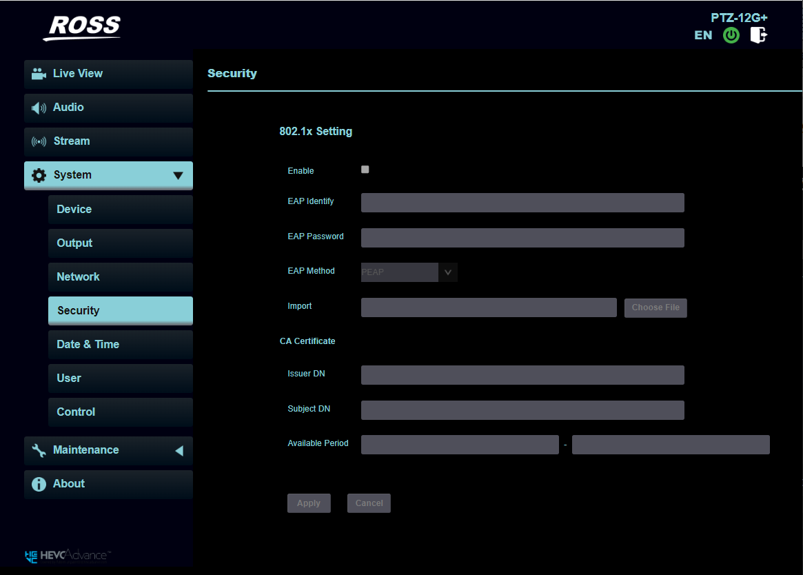
Figure 17 - System: Security Page
Table 11
System: Date & Time
This section describes features available on the System: Date & Time page (Figure ??).
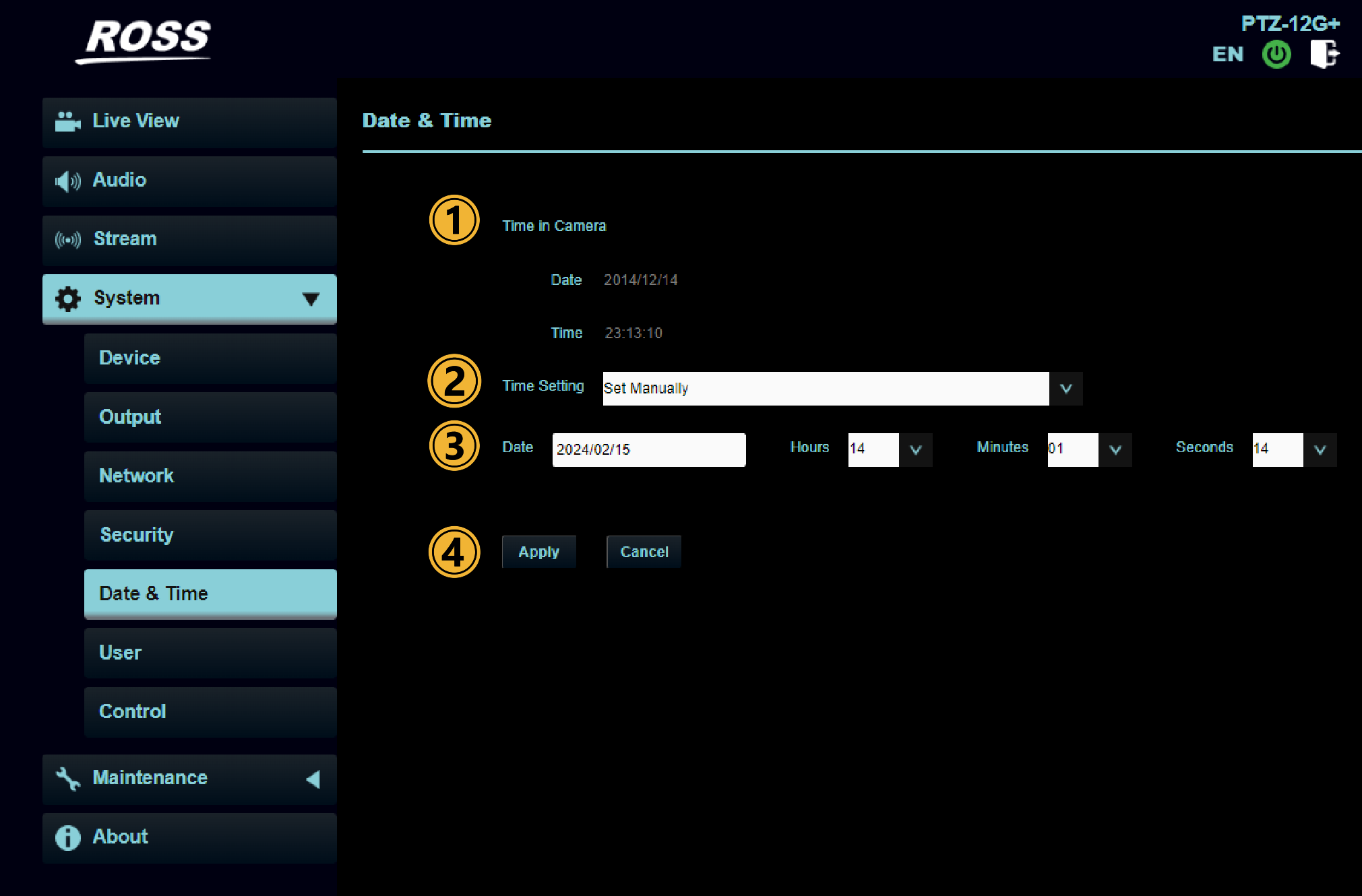
Figure 18 - System: Date & Time Page
Table 12
System: User
This section describes features available on the System: User page (Figure ??).
This allows you to add user accounts and assign permissions to them.
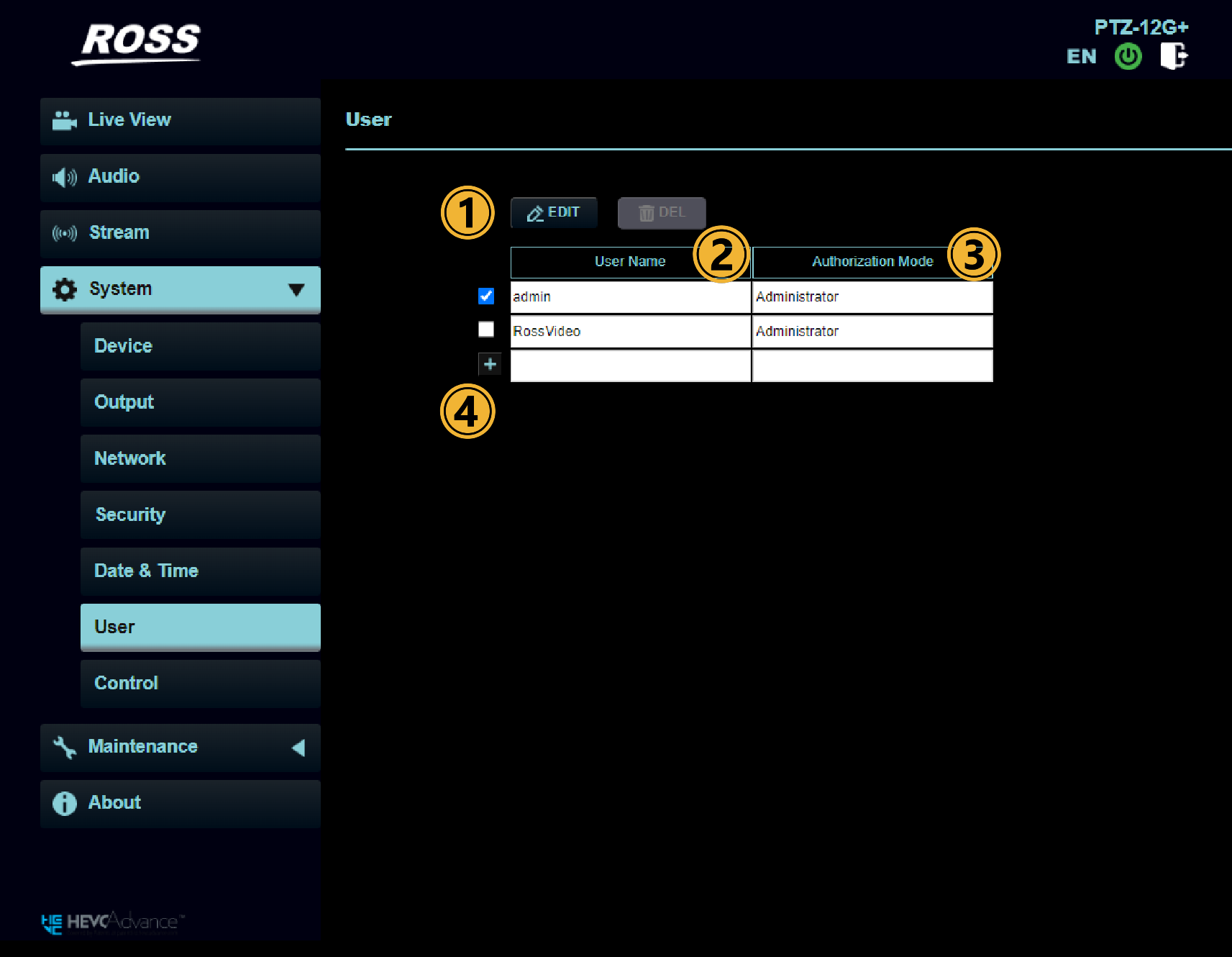
Figure 19 - System: User Page
Table 13
| No | Item | Function Descriptions |
|---|---|---|
| 1 | Edit/Delete User | Select Edit to open the Edit User Page: 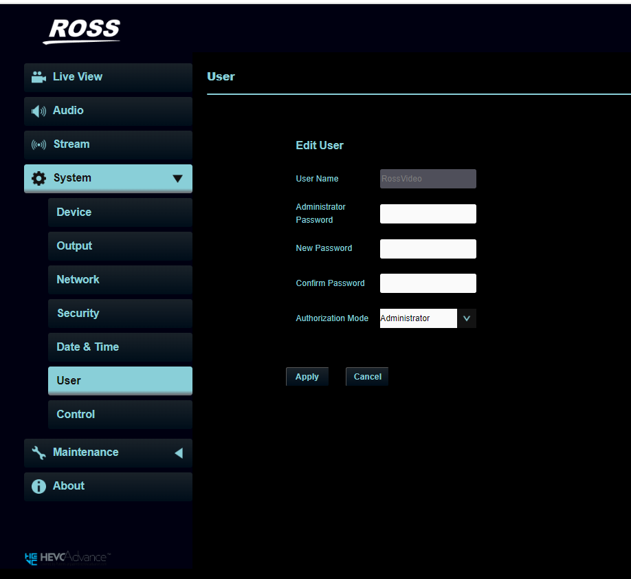 Note: Select the check box beside the row you wish to edit or delete before selecting Edit.
Note: Passwords cannot contain special characters and must be between 4 and 32 characters in length. |
| 2 | User Name | Shows all authorized users. Use the + to add a new user or Edit button to edit an existing user. Note: Use only letters and numbers. No symbols. |
| 3 | Authorization Mode | All authorization modes can view live video (available with NDI|HX disabled.).
|
| 4 | + (Add user) | Select + to add a new user. A page will open to let you set the User Name, Password and Authorization mode for the new user. |
System: Control
This section describes features available on the System: Control page (Figure ??).
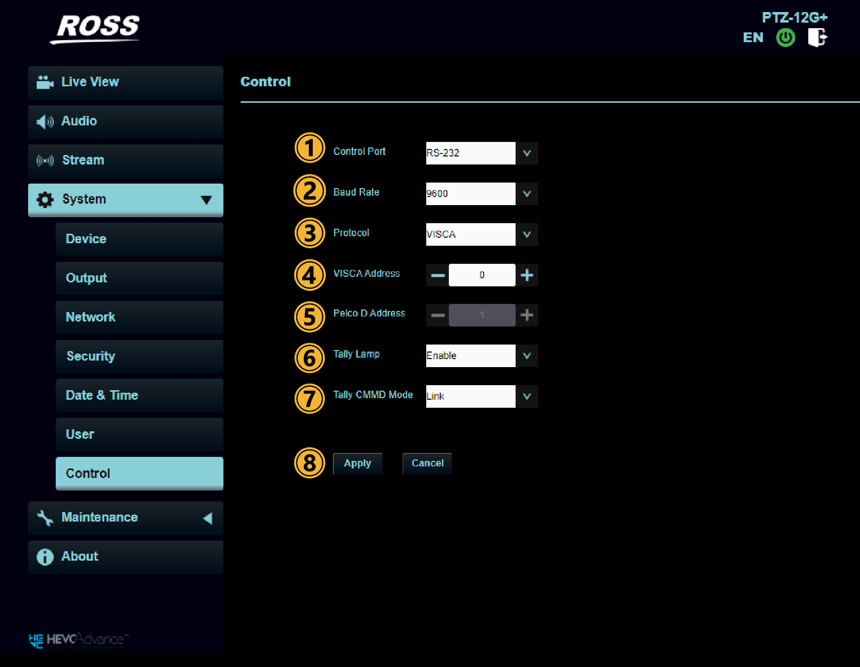
Figure 20 - System: C ontrol Page
Table 14
| No | Item | Function Descriptions |
|---|---|---|
| 1 | Control Port | Control Port is only used when cameras are connected using serial cables (RS-232 or RS-422). |
| 2 | Baud Rate | Choose the transmission speed of the control signal. VISCA typically uses 9600 baud. |
| 3 | Protocol | VISCA / Pelco D Note: To control PTZ-12G+ cameras using the DashBoard PTZ Camera Control Plugin, Protocol must be set to VISCA. |
| 4 | VISCA Address | The camera ID address 0 ~ 7 can be assigned. Note: The VISCA Address for serial has no impact on IP VISCA. |
| 5 | Pelco D Address | The camera ID address 1 ~ 255 can be assigned. |
| 6 | Tally Lamp | Enable/Disable Tally Lamp |
| 7 | Tally CMMD Mode | Impacts how the camera handles tally commands from a VISCA controller. Use normal operation, unless otherwise specified by the controller software manufacturer.
|
| 8 | Apply/Cancel | Select Apply to save changes. |
Maintenance Page
This section describes features available on the M aintenance page (Figure ??).
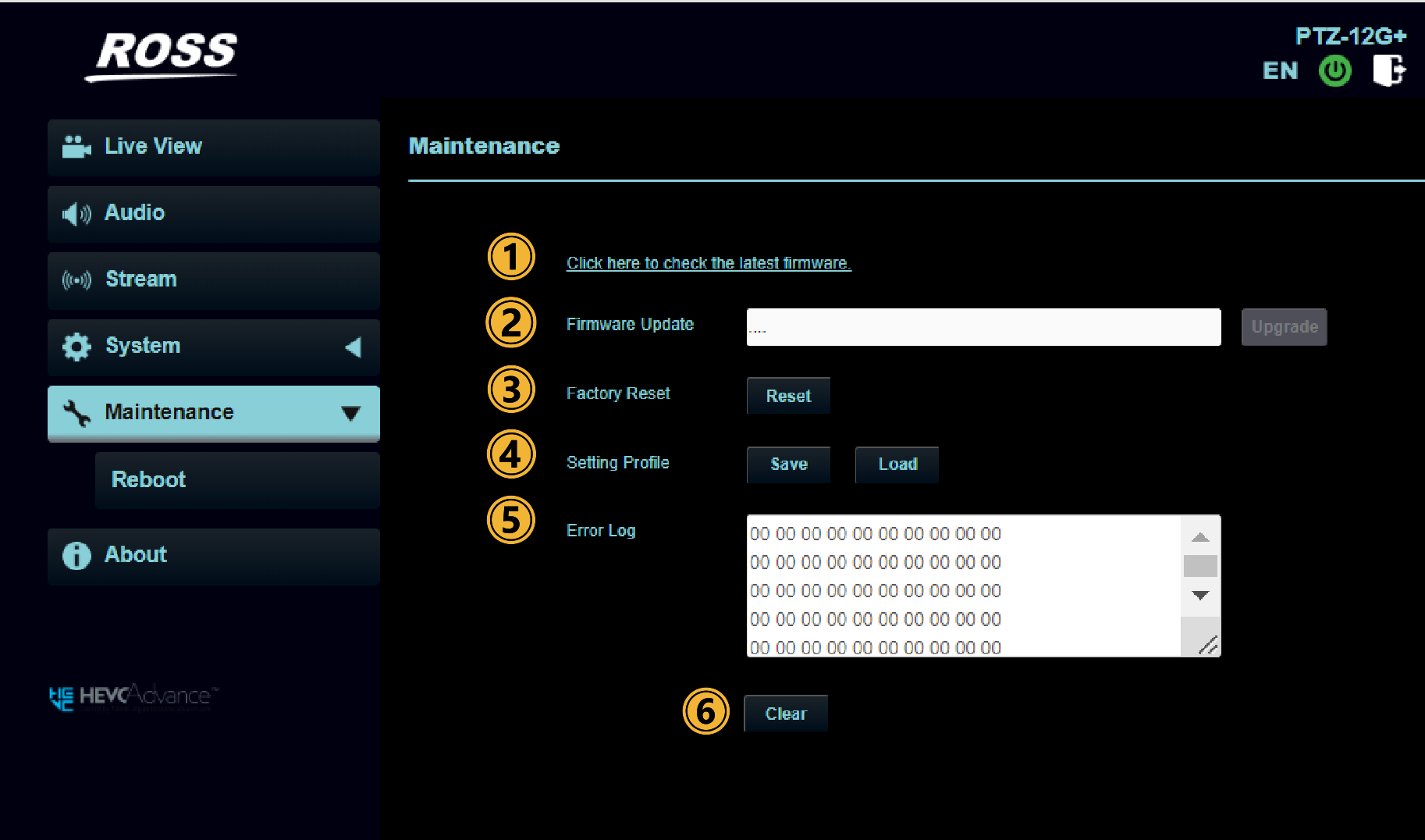
Figure 21 - Maintenance Page
Table 15
| Number | Item | Function Description |
|---|---|---|
| 1 | Click here to check the latest firmware | This link will take you to the Ross website where you can check for the latest available firmware. The currently running version can be found on the About page in the camera web UI. |
| 2 | Firmware Update | Click in the text field to open a browser that will let you navigate to the correct firmware file. Select Upgrade to update the firmware. Note: Update takes about 2 - 3 minutes Important: Do not operate or turn off the power of the device during the update to avoid firmware update failure |
| 3 | Factory Reset | All Network Settings reset to DHCP including High Bandwidth NDI & FreeD.
|
| 4 | Setting Profile | Save and load camera settings from file. |
| 5 | Error Log | If the camera encounters errors, an error code log will be established. |
| 6 | Clear | When an error code appears, please try to click Clear to make sure whether the issue has occurred repetitively. |
Maintenance: Reboot
This section describes features available on the Maintenance > Reboot page (Figure ??).
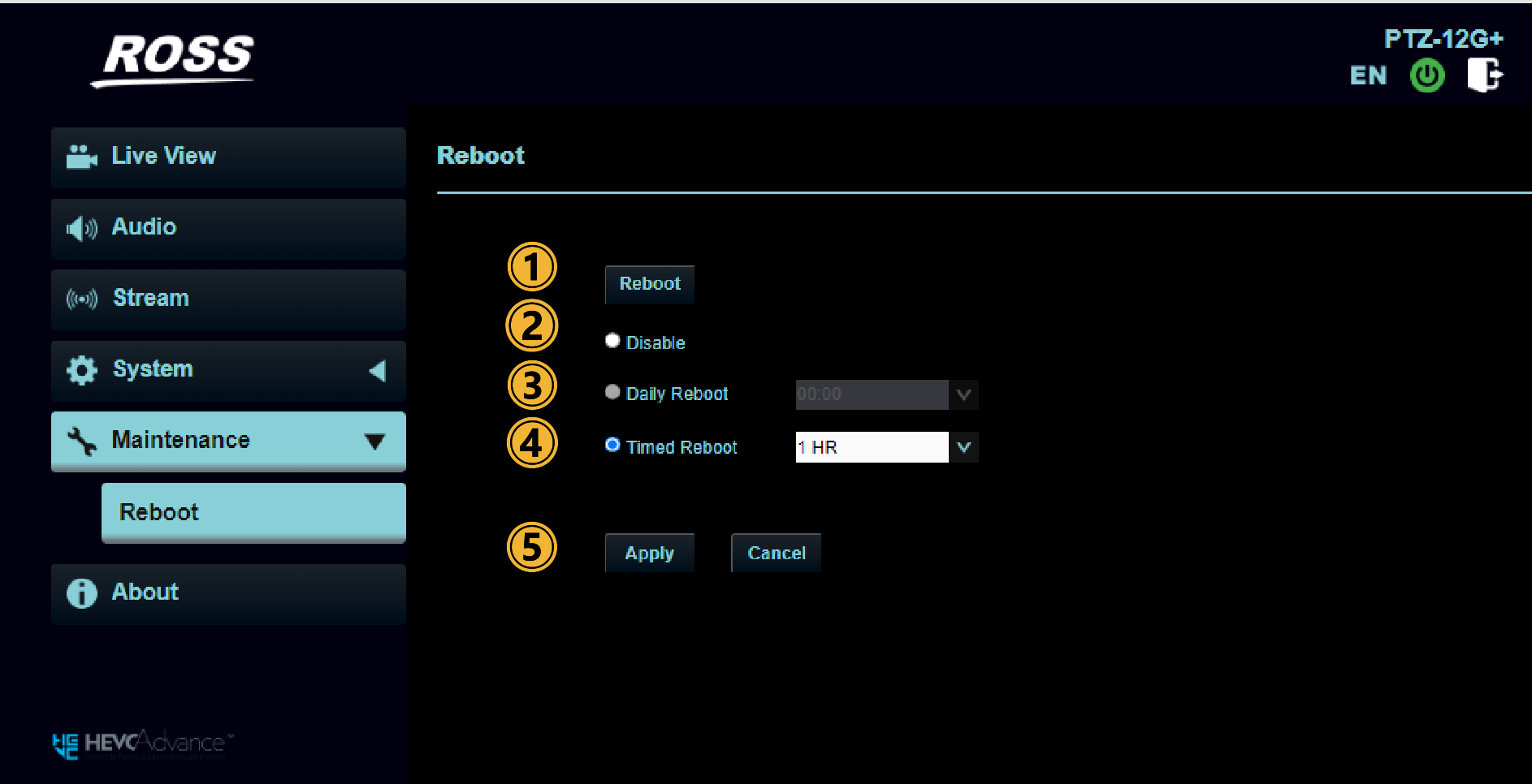
Figure 22 - Maintenance > Reboot Page
Table 16
| Number | Item | Function Descriptions |
|---|---|---|
| 1 | Reboot | Reboots the PTZ camera. |
| 2 | Disable | Disable the reboot settings. |
| 3 | Daily Reboot | Set the daily reboot time. Note: Daily reboot only available when Time Setting on the System > Date & Time page is set to Synchronized with SNTP server. |
| 4 | Timed Reboot | Select Timed Reboot to reboot the camera at regular intervals. |
| 5 | Apply/Cancel | Select Apply to save changes. |
About Page
This section describes features available on the About page (Figure ??).
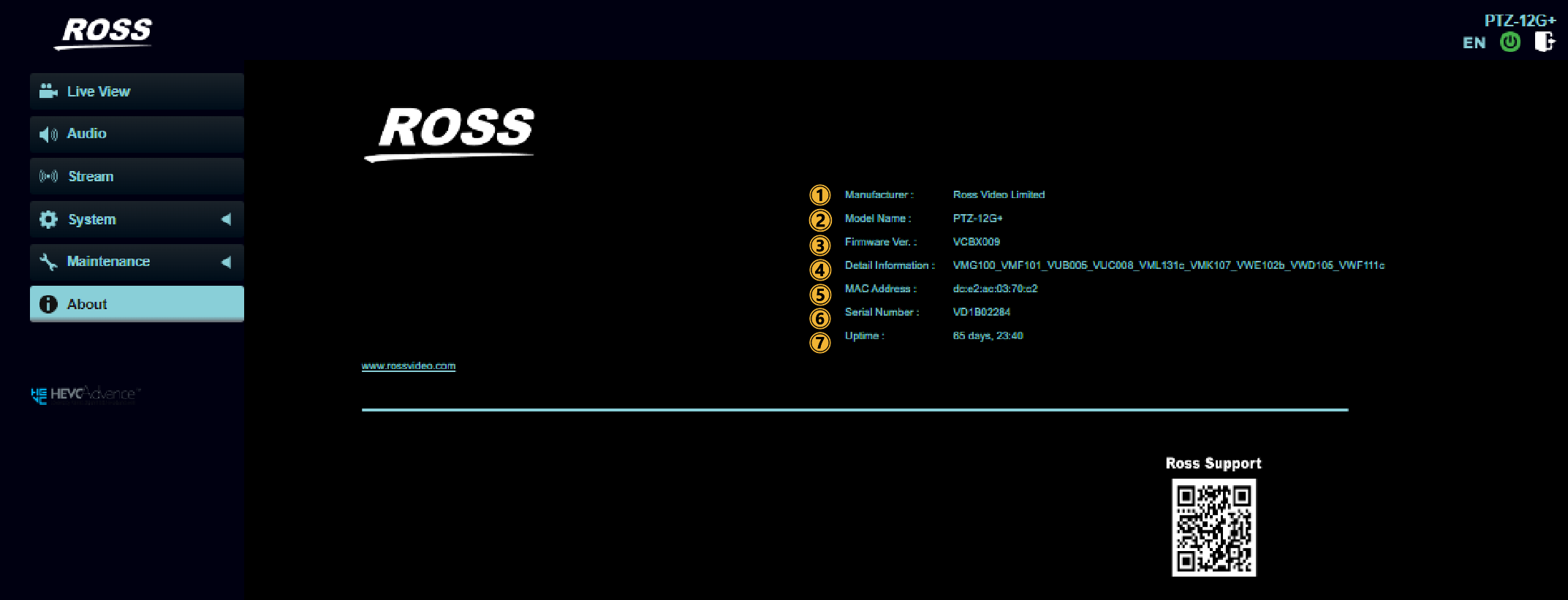
Figure 23 - About Page
Table 17
| No | Item | Function Descriptions |
|---|---|---|
| 1 | Manufacturer | Displays the manufacturer name. |
| 2 | Model Name | Displays the device model name. |
| 3 | Firmware Version | Displays the firmware version installed on the camera. |
| 4 | Detail Information | Displays list of individual firmware components included in the installed firmware version. |
| 5 | MAC Address | A MAC address is a unique identifier assigned to network-connected devices. It consists of a 12-digit number in hexadecimal format. |
| 6 | Serial No. | Displays the camera serial number. |
| 7 | Uptime | Displays the amount of time since the last power cycle. |
Viewing RTSP Video Stream
NDI|HX2 or HX3 must be disabled to use this setting.
High Bandwidth NDI can be used at the same time as video streaming.
You can view this video output in an RTSP-compatible playback application such as VLC media player.
To view the RTSP stream in VLC media player:
-
In the camera’s web interface, navigate to Settings > Outp ut .
-
Set the resolution.
-
Set the Output Sourc e to HDMI + Streaming .
-
Navigate to S trea m .
The Video page appears (Figure ??).
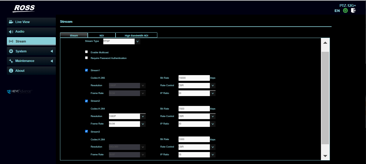
Figure 24 - St ream Page
-
Configure settings for each video stream (1, 2, 3), as required
-
In VLC media player, open a network stream, and specify the URL for the stream:
- Stream 1 — Main Streaming (@H.265) — rtsp:// camera_IP :8554/hevc
- Stream 2 — Sub1 Streaming (@H.264) — rtsp:// camera_IP :8557/h264
- Stream 3 — Sub2 Streaming (@H.264) — rtsp:// camera_IP :8556/h264
noteIn the paths listed above, replace camera_IP with the IP address of the PTZ camera.
Figure ?? and Figure ?? show how to open a network stream and specify the URL for Stream 1 , based on a camera with an IP address of 192.168.4.48 .
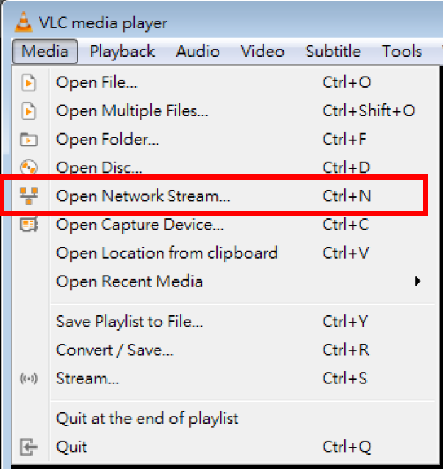
Figure 25 - Opening a Network Stream in VLC Media Player
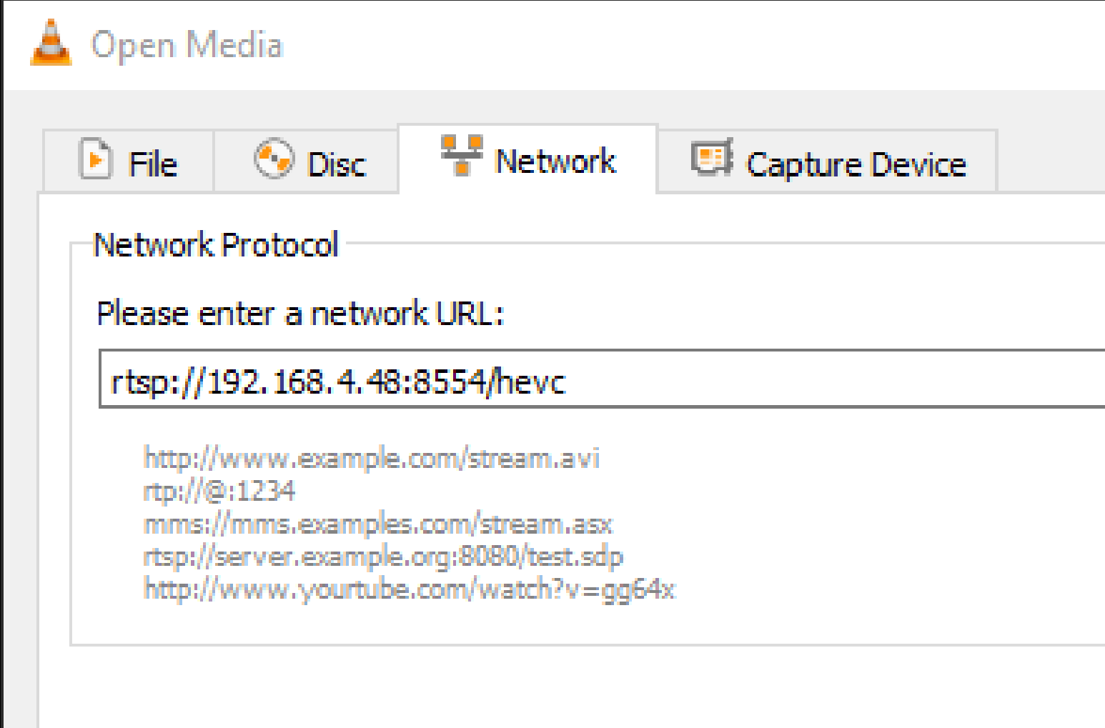
Figure 26 - Specifying a Stream URL in VLC Media Player
Specifications
Table 18
| Item | Specification |
| Image Sensor | 1/1.8 inch, 9.17Mpixel, RS CMOS |
| Video Output | HDMI : V2.0 4K 60p |
| Ethernet, USB3.0 | |
| 3G-SDI, 12G-SDI: 4K 60p | |
| IP Stream | HEVC: 4K 60p NDI & RTSP |
| H.264: 640X360 29.97fps NDI | |
| H.264: 1080p59.94fps RTSP | |
| H.264: 640X360 29.97fps RTSP | |
| Video Output | Ethernet / 12G-SDI / 3G-SDI / HDMI2.0 / USB 3.0 |
| Video Output connections | HDMI2.0 X1, BNC X2 |
| Optical Zoom | 30x |
| Digital Zoom | 12x |
| Horizontal Viewing Angle | 63° (Wide) to 3.7° (Tele) |
| Vertical Viewing Angle | 35.4° (Wide) to 2.1° (Tele) |
| Panning speed | 0.01°~300°/sec |
| Panning Angle | +170° ~ -170° |
| Tilting Angle | +90° ~ -30° |
| Tilting Speed | 0.01°~300°/sec |
| Lens Focal length | 6.5mm ~ 202mm |
| Lens Aperture | F1.6 @ 6.5mm ~ F4.8 @ 202mm |
| Shutter Speed | 1/1 ~ 1/10,000 sec |
| Minimum Object Distance | 1.5m (Wide / Tele) |
| Minimum Illumination | 0.05 lux (F1.6, 50IRE, 30fps) |
| Video S/N Ratio | >50dB |
| Focus System | Auto, Manual, Smart AF |
| Gain Control | Auto / Manual |
| White Balance | Auto / Manual |
| Exposure Control | Auto / Manual / Smart AE |
| Digital WDR | Yes |
| 3D NR | Yes |
| Image Flip | Yes |
| Preset position memories | 256 (on-board) |
| Unlimited with DashBoard or SmartShell control system | |
| Audio Compression Format | IP: G.711, USB: PCM |
| Control Protocols | VISCA / VISCA IP / PELCO-D / NDI / UVC/ UAC |
| Serial Control | RS-232 or RS-422 |
| Tally Indicator | Yes: Front |
| PoE | High Power PoE++ (IEEE802.3bt) |
| Network Streaming Protocols | Full NDI / NDI|HX3 / NDI|HX2 / RTSP / RTMP / RTMPS / MPEG-TS / SRT |
| Video Compression types | HEVC/ H.265: 2160p 60 |
| H.264: 2160p 30 | |
| MPEG: 1080p 30 | |
| Audio Input | Line In/MIC In, 3.5mm x1 |
| IR Pass-through | No |
| IR Receiver | Yes |
| IR Remote Control | Yes |
| IQ Sync | Yes |
| Color Space | Standard |
| Genlock | VBS, TLS |
| AR/VR data out | FreeD, IP or Serial data |
| Storage temperature | –20°C to +60°C (-4°F to 140°F) |
| Operating temperature | 0°C to 40°C (32°F to 104°F) |
| Power Consumption | DC: ≦31W ,PoE++: ≦33W |
| Weight | 6.6 lbs. (3 kg) |
| Dimensions | 9.1" x 7.4" x 7.4" |
| (232 x 188 x 189mm) |