Appendix A: Serial Connections
This appendix provides information about pin assignments for controlling PTZ-12G+ over serial RS-232 and serial RS-422.
The DashBoard PTZ Camera Control plugin does not support serial connections. DashBoard communicates with PTZ cameras via VISCA over IP.
Topics include the following:
-
Figure ?? shows the RS-232 and RS-422 connectors on the back of the camera.
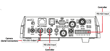
Figure 1 - Serial RS-232 and RS-422 Connectors
RS-232 Serial Connections
This section describes connections for serial control of PTZ-12G+ cameras over RS-232.
It includes the following topics:
- “RS-232 IN — Pin Assignments”
- “RS-232 OUT — Pin Assignments”
- “RS-232 — Connecting Camera to Computer”
- “RS-232 — Cascading Camera Connections”
RS-232 IN — Pin Assignments
Figure ?? details the pin assignments for the RS-232 IN connector on the camera.
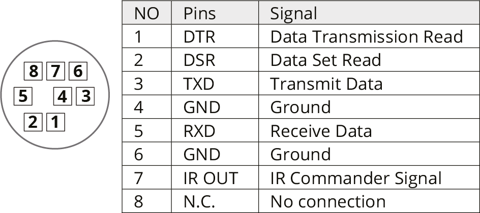
Figure 2 - Pin Assignments for RS-232 IN Connector
RS-232 OUT — Pin Assignments
Figure ?? details the pin assignments for the RS-232 OUT connector on the camera.
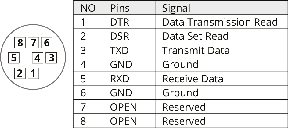
Figure 3 - Pin Assignments for RS-232 OUT Connector
RS-232 — Connecting Camera to Computer
Figure ?? details pin connections required between the camera and a computer that controls it over serial RS-232.
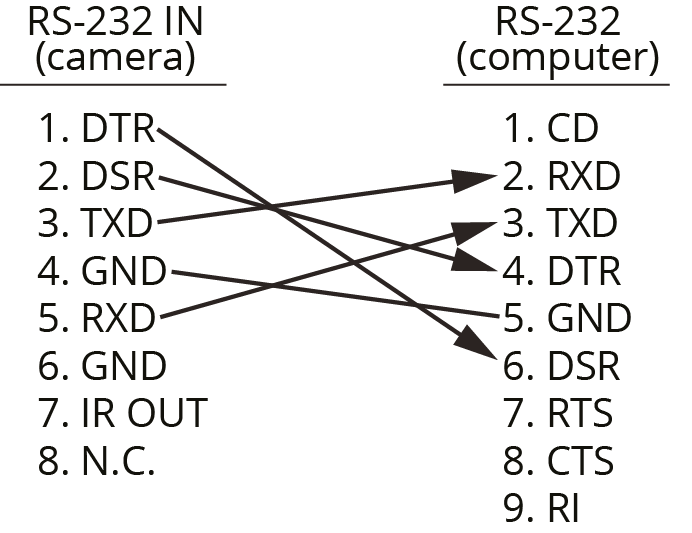
Figure 4 - Connecting Camera to Control Computer for RS-232 Control
RS-232 — Cascading Camera Connections
Figure ?? details pin connections required to cascade (daisy-chain) up to seven cameras for control over serial RS-232.
If you plan to control the cameras using DashBoard, the control Protocol on each camera must be set to VISCA , and the VISCA Address setting on each camera must be unique. For information about accessing these settings using the web interface, see “System: Control”.
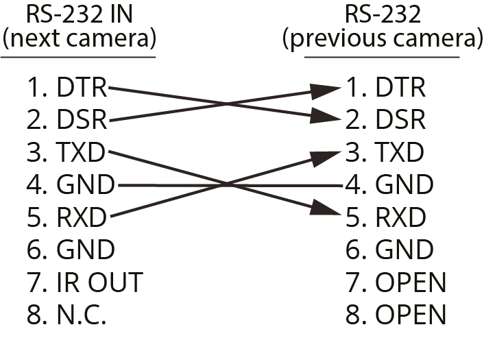
Figure 5 - Cascading Camera Control over RS-232
RS-422 Serial Connections
This section describes connections for serial control of PTZ-12G+ Cameras over RS-422.
It includes the following topics:
- “Making RS-422 Pin Connections”
- “RS-422 Connector — Pin Assignments”
- “RS-422 — Cascading Camera Connections”
Making RS-422 Pin Connections
The camera comes with an RS-422 connector that mates with the RS-422 connector on the camera (Figure ??). The connector accepts AWG 28 to AWG 18 wire.
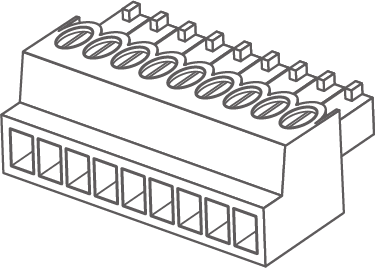
Figure 6 - RS-422 Connector (included)
To wire the RS-422 connector:
-
For each connection:
- Strip the wire insulation to expose 6mm (1/4”) of bare wire.
- Insert the bare wire into the correct terminal hole.
- Use a small slot screwdriver to tighten the terminal screw to secure the wire.
To attach the RS-422 connector to the camera:
-
Hold the camera base securely.
importantNever handle or rotate the camera head. Handling or rotating the camera head by hand can permanently damage the camera.
-
Align the connector with the RS-422 connector on the camera.
tipThe terminal screws face upwards, towards the top of the camera.
-
Press the connector firmly into the camera.
RS-422 Connector — Pin Assignments
This section details the pin assignments for the RS-422 connector on the back of the camera.
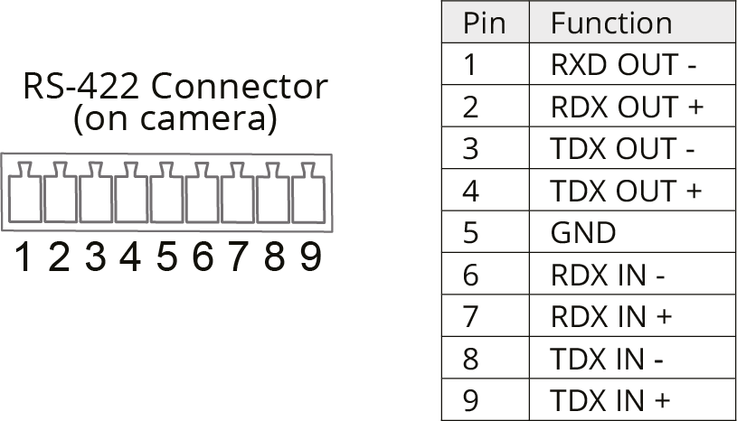
Figure 7 - Pin Assignments for RS-422 Connector
RS-422 — Cascading Camera Connections
Figure ?? details pin connections required to cascade (daisy-chain) up to seven cameras for control over serial RS-422.
If you plan to control the cameras using DashBoard, the control Protocol on each camera must be set to VISCA , and the VISCA Address setting on each camera must be unique. For information about accessing these settings using the web interface, see “System: Control”.
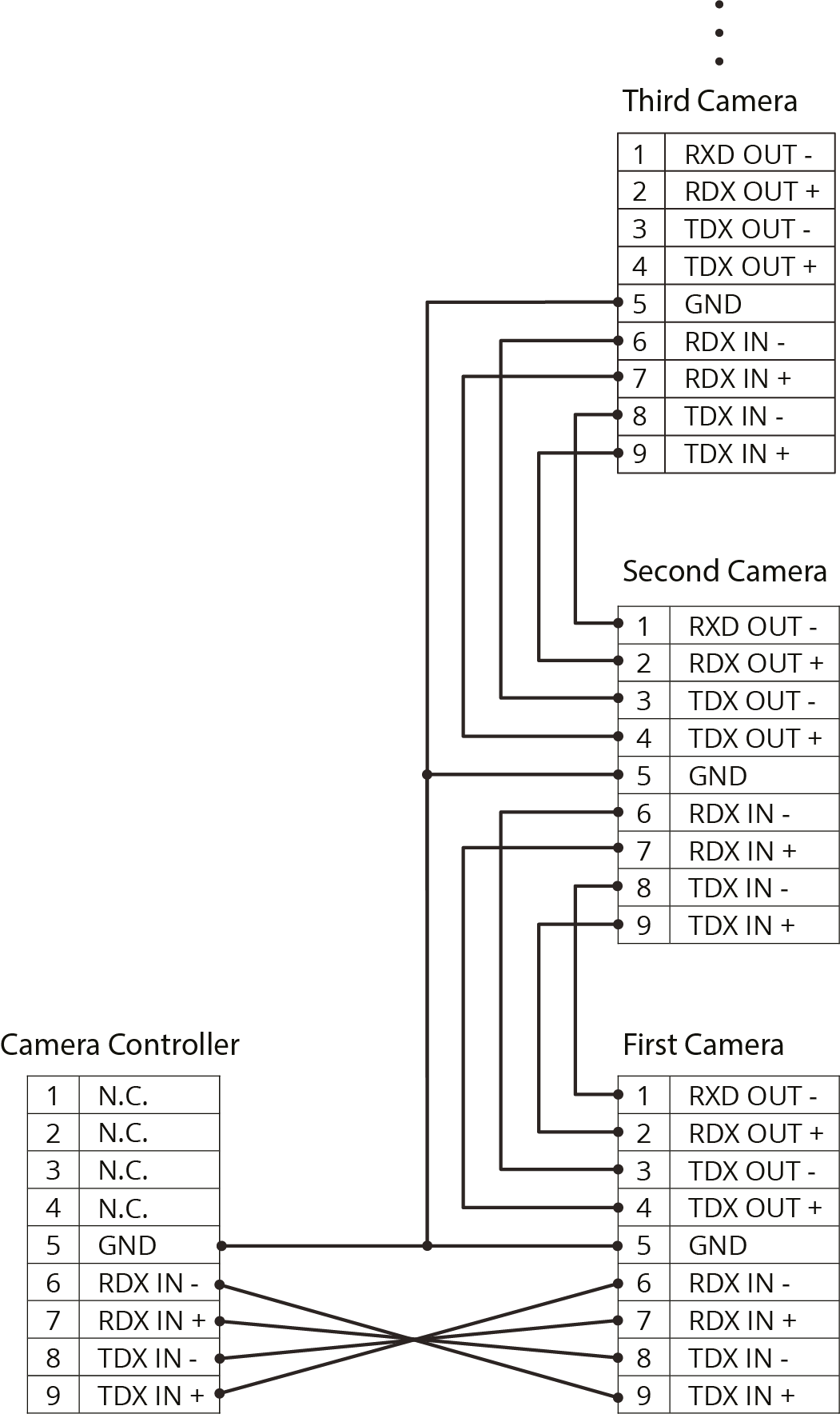
Figure 8 - Cascading Camera Control over RS-422
Appendix B: Genlock Input Support
Genlock Input Support
This section describes the Genlock Input support signal formats.
Table 1 - Genlock Input Support Formats
| Signal Output Format | Genlock External Sync Signal Input Format | |
|---|---|---|
| Tri-level Sync | ||
| 2160P | 59.94 | 480i@59.94 |
| 1080i@59.94 | ||
| 50 | 576i@50 | |
| 1080i@50 | ||
| 29.97 | 480i@59.94 | |
| 1080i@59.94 | ||
| 25 | 576i@50 | |
| 1080i@50 | ||
| 1080P | 59.94 | 480i@59.94 |
| 1080i@59.94 | ||
| 50 | 576i@50 | |
| 1080i@50 | ||
| 29.97 | 480i@59.94 | |
| 1080i@59.94 | ||
| 25 | 576i@50 | |
| 1080i@50 | ||
| 720P | 59.94 | 480i@59.94 |
| 1080i@59.94 | ||
| 50 | 576i@50 | |
| 1080i@50 | ||
| 29.97 | 480i@59.94 | |
| 1080i@59.94 | ||
| 25 | 480i@50 | |
| 1080i@50 | ||
| 1080i | 59.94 | 480i@59.94 |
| 1080i@59.94 | ||
| 50 | 576i@50 | |
| 1080i@50 | ||