Camera Installation
This section describes how to install PTZ-12G+ Cameras.
For information about upgrading firmware on a camera that is already operational, see “Maintenance Page”.
Before you begin:
-
Read the safety instructions. See “Safety Instructions”.
-
Determine the installation location:
- The camera can be placed on a stable horizontal surface or tripod, mounted to a ceiling (inverted), or mounted to a wall (special wall-mount bracket PTZ-WB-BLACK is required).
- The camera base must be horizontal, and not on an angle.
- The camera must be positioned an appropriate distance from the subject (minimum 2m (79”). The lens field of view is 3° (tele) to 63° deg (wide).
- The camera must be positioned away from other lights sources that might interfere with the video image.
- The installation location must provide adequate space for connecting cables to the back of the camera.
- Ensure that the installation location conforms to the safety instructions. See “Safety Instructions”.
-
Ensure that you have the necessary knowledge and skills:
-
If the camera is to be fastened to a wall or ceiling, you need to select and install appropriate fastening hardware, and possibly work at heights.
-
Configuring the camera requires basic computer networking skills, such as configuring IP connections.
Perform all procedures in the order presented.
The main installation steps described in this section are as follows:
-
Set the IR Select Switch
The remote control unit uses infra-red (IR) signals to communicate with cameras. A single remote control unit can control up to three cameras in an area.
The IR SELECT switch on the back of the camera assigns a Camera select number (1 , 2 , or 3 ) to the camera (Figure ??).

Figure 1 - The IR Select Switch on the Back of a Camera
To assign Camera select numbers for remote control:
-
For each camera in an area, set the IR SELECT switch to a different number (1 , 2 , or 3 ).
tipIf there are more than three cameras in an area, assign different numbers to cameras that are near each other.
When you later use the remote control unit, you can press a Camera select button (1 , 2 , or 3 ) to specify which camera you want to control (Figure ??).
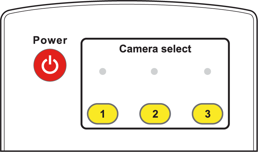
Figure 2 - Remote Control Unit, showing Camera select buttons (1, 2, 3)
Using the DashBoard PTZ Camera Control plugin, you can disable remote control reception to prevent accidental changes being made by remote control. For more information, see “DashBoard Control”, and the User Manual for PTZ Camera Control Plugin (8351DR-015) .
Set the Video Output Switch
If you know which video format you want the camera to output, set the OUTPUT SWITCH (dial) on the back of the camera.
To set the video output switch:
- Use a small slot screwdriver to gently rotate the OUTPUT SWITCH until the arrow points to the letter that represents the desired video format. (Figure ??).
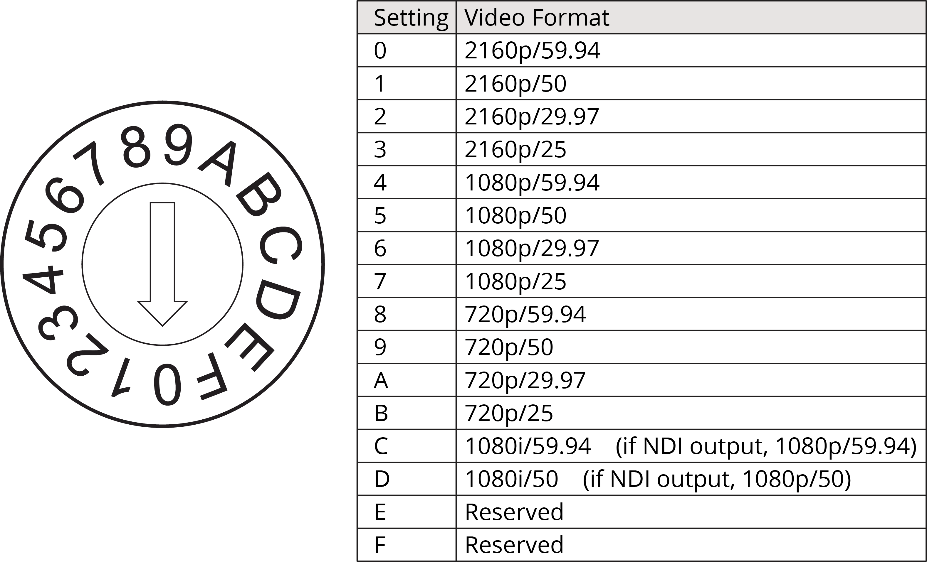
Figure 3 - OUTPUT SWITCH Settings and Video Formats
-
The factory-set default position is 0 — 2160p/59.94 .
tipAlternatively, you can set the video output format later using the remote control unit, the web interface, or the DashBoard PTZ Camera Control plugin.
noteThe switch position may not reflect the current output format. Resolution changes made in the On-Screen Display menu, the web interface, or the DashBoard PTZ Camera Control plugin override the Output Switch .
Configure Network Settings
Each device on an IP network must have a unique IP address.
All PTZ-12G+ Cameras are shipped in DHCP mode, and with the same default static IP address assigned (192.168.100.100 ).
You can use the cameras in DHCP mode, or configure a unique static IP address for each camera.
Using DHCP mode requires a DHCP server on the network, with enough available IP addresses for the number of cameras.
If you are installing multiple cameras, we suggest you use the remote control unit and On-Screen Display menu to configure network settings for each camera before you install them.
For each camera, ensure the IP address is accessible to computers and other devices that will control that camera.
To avoid accidentally configuring multiple cameras identically, ensure that any other cameras that have the same Camera select number (1 , 2 , or 3 ) are either powered off or not within range of the IR signal of the remote control unit.
To configure network settings:
-
Place the camera on a desk or table.
-
Connect the camera’s video output (HDMI or SDI) to a video monitor.
-
Connect power to the camera.
The camera initializes and moves to its home position.
Video from the camera appears on the video monitor.
tipSome monitors cannot render all video output formats. If video does not appear on the monitor within 30 seconds, adjust the Output Switch on the back of the camera to a format the monitor can render.
-
On the remote control unit, press the appropriate Camera select button (1 , 2 , or 3 ).
-
Press the Menu button.
The menu appears on the monitor.
tipPress the up and down arrow buttons to navigate through the menu options.
-
Navigate to the Ethernet menu option.
-
 Press the center Home - Enter button.
Network settings appear.
-
Use the arrow buttons on the remote control unit to configure the network settings as required.
-
Press the Menu button to return to the main menu, and then press it again to close the menu.
Mount the Camera
You can install the camera on a desk or table, on a tripod, on a ceiling, or on a wall.
When handling the camera, lift it by the base only. Never handle or rotate the camera head. Handling or rotating the camera head by hand can permanently damage the camera.
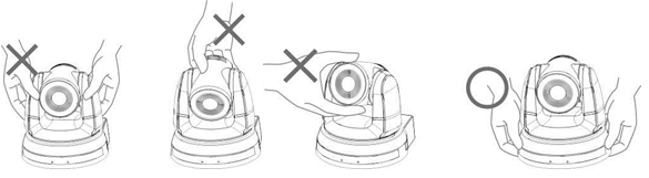
Figure 4 - Proper Handling of the Camera
This section includes the following topics:
- “Place the Camera on a Desk or Table”
- “Mount the Camera on a Tripod”
- “Mount the Camera on a Ceiling”
- “Mount the Camera to a Wall”
After you install the camera, you can attach a Kensington lock for security purposes.
Place the Camera on a Desk or Table
Place the camera on a stable, flat, horizontal surface such as a desk or table.
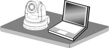
Figure 5 - Installing the Camera on a Desk or Table
Mount the Camera on a Tripod
The camera base has a standard 1/4-20 UNC hole for mounting the camera on a tripod (Figure ??).
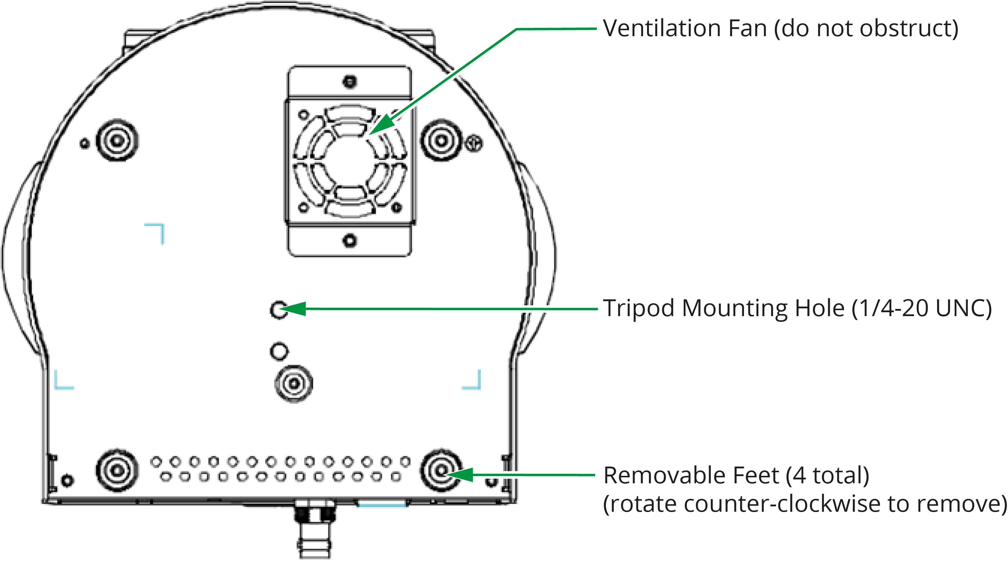
Figure 6 - Mounting the Camera on a Tripod
A tripod mount adapter is required to secure the camera to the tripod (Figure 6)..
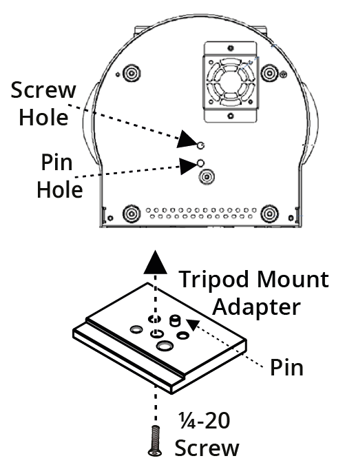
Figure 7 - Mounting the Camera on a Tripod
When mounting the tripod mount adapter on the camera:
-
Screw the tripod mount adapter onto the camera with the ¼-20 UNC screw.
-
Align the threaded hole on the bottom of the adapter with the tripod screw and tighten.
When mounting the camera on a tripod:
-
Ensure that the tripod is stable and level.
-
Use only a standard ¼-20 UNC tripod screw. Do not over-tighten.
-
Ensure that the ventilation fan on the bottom of the camera is not obstructed.
Mount the Camera on a Ceiling
You can invert the camera and mount it on a ceiling.
The camera must be mounted horizontally. Do not mount it on a sloped ceiling.
The camera package includes hardware for mounting the camera on a ceiling (Figure ??).
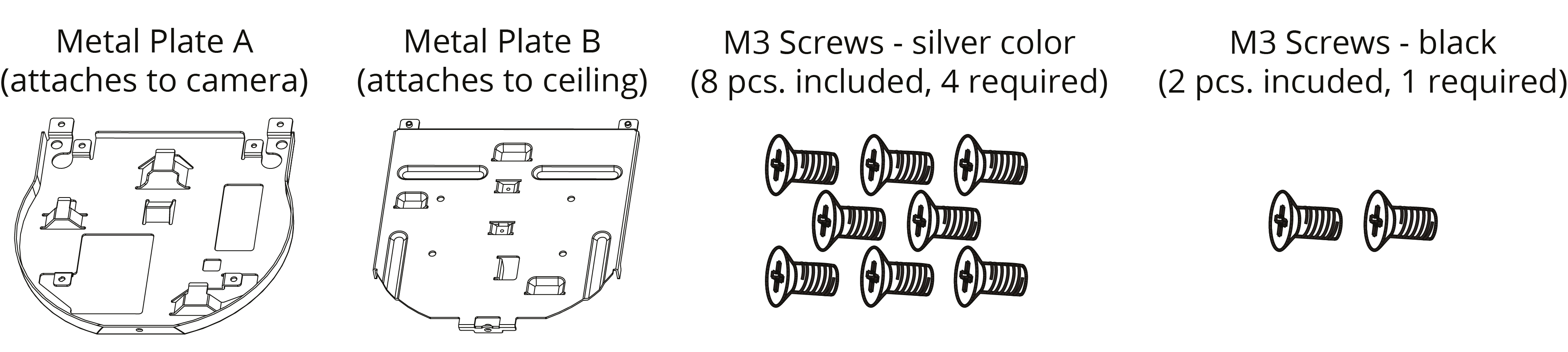
Figure 8 - Ceiling Mounting Hardware Included with the Camera
To mount the camera, you fasten Metal Plate A to the camera, and mount Metal Plate B to the ceiling (additional fasteners required). You then fasten the two metal plates together.
This section provides instructions for mounting the camera to a ceiling. Read all steps before you begin.
To mount the camera on a ceiling:
-
Remove the feet (4 pcs) from the bottom of the camera by rotating them counter-clockwise (Figure ??).
Store the feet for future use.
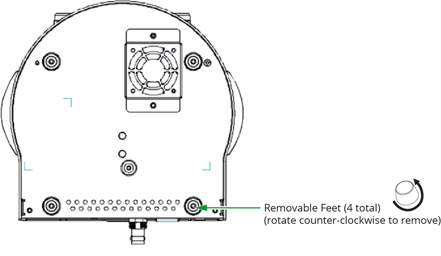
Figure 9 - Bottom View of Camera, showing Removable Feet (4pcs)
-
Using four silver M3 screws (included), fasten Metal Plate A to the base of the camera (Figure ??).
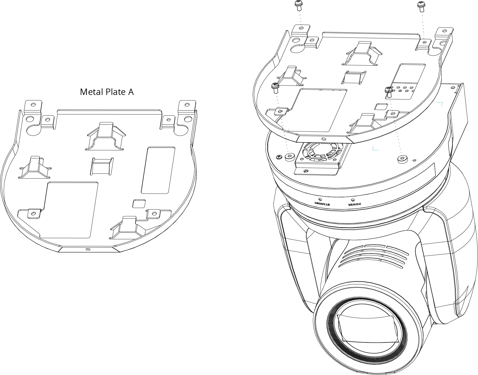
Figure 10 - Attaching Metal Plate A to the Base of the Camera (4 silver M3 screws - included)
-
Mount Metal Plate B on the ceiling, using suitable fasteners (Figure ??).
noteFasteners are not included. Use only fasteners that are suitable for the mounting surface and for the weight of the camera (approximately 3kg (6.6 lbs)). The diameter of the mounting holes on Metal Plate B is 4.5mm (5/32”).
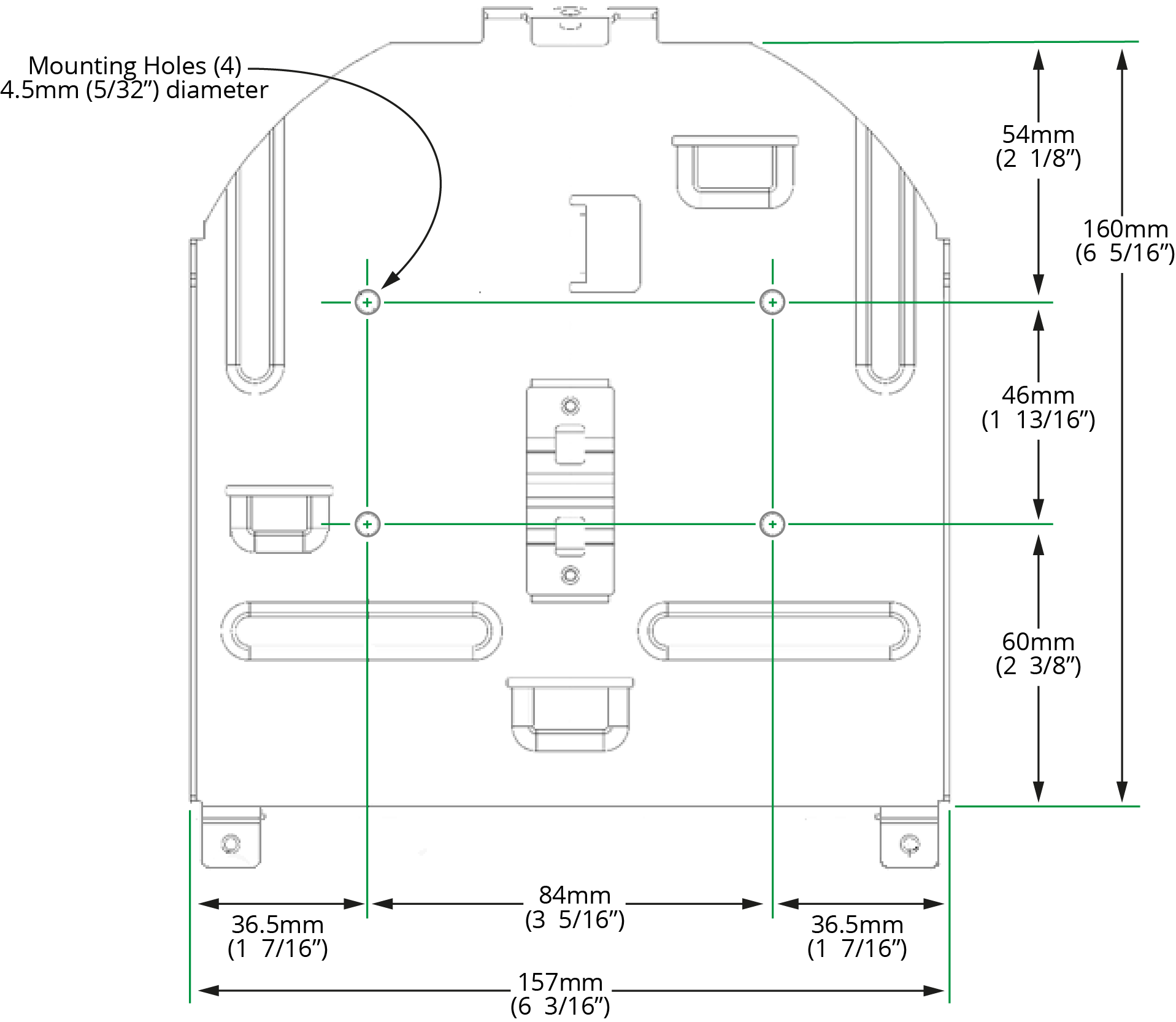
Figure 11 - Metal Plate B, showing Mounting Holes
-
Align the two metal plates and then fasten them together using two silver M3 screws (back) and one black M3 screw (front). Screws are included. See Figure ??.
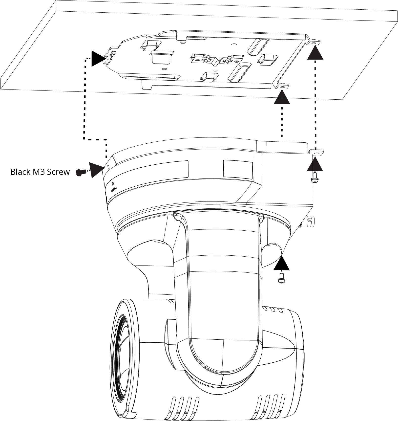
Figure 12 - Fastening Mounting Plates Together, to Mount the Camera to the Ceiling
Mount the Camera to a Wall
Mounting the camera to a wall requires a special wall-mount bracket, available from Ross Video (PTZ-WB-BLACK ).
The wall must be sturdy and the mounting surface must be capable of supporting the weight of the camera (approximately 3kg (6.6 lbs) plus wall-mount bracket).
The camera must be mounted horizontally. Do not mount it directly on a wall.
For more information, contact Ross Video.
Connect Power and Network Cables
You can power the camera using the provided 12 VDC power supply unit, or by connecting the camera to a network connection that supports Power over Ethernet (PoE++).
You can control the camera over an Ethernet connection or a serial connection (RS-232 or RS-422).
Figure ?? shows cable connectors on the back of the camera.
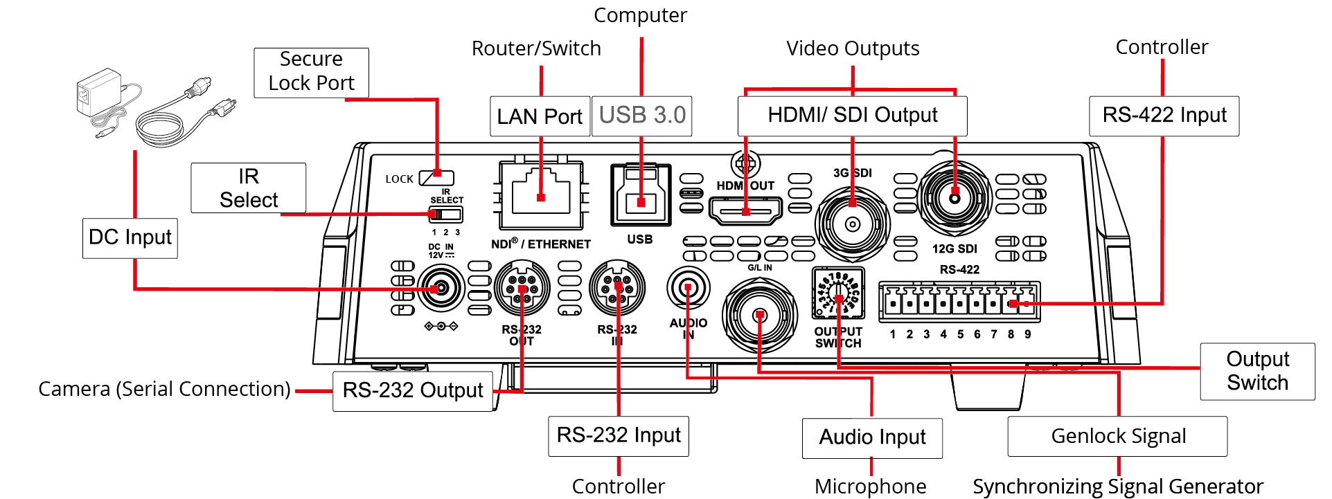
Figure 13 - Rear View of the Camera, showing Connectors
To provide power to the camera, do one of the following:
-
Connect the provided 12 V DC power supply unit to the DC IN connector on the camera.
-
Using CAT6 network cable, connect the Ethernet port of the camera to a network router or hub that supports Power over Ethernet (PoE).
The camera requires PoE++ (IEEE802.3bt).
To control the camera over Ethernet:
- Connect the Ethernet port of the camera to a network router or hub.
To control the camera over serial RS-232:
-
Connect a serial cable to the RS-232 IN port on the back of the camera.
tipYou can cascade (daisy-chain) one serial RS-232 control line to as many as seven cameras. To cascade serial RS-232 control, connect a serial cable from the RS-232 OUT port of the current camera to the RS-232 IN port of the next camera.
For information about pin assignments for serial RS-232 control, see “Appendix A: Serial Connections”.
To control the camera over serial RS-422:
-
Create an RS-422 control cable and then connect it to the RS-422 connector on the back of the camera.
tipYou can cascade (daisy-chain) one serial RS-422 control line to as many as seven cameras.
For information about pin assignments for serial RS-422 control, and about creating an RS-422 control cable, see “Appendix A: Serial Connections”.
Connect Video Output
Connect cables to video output connectors as required (see Figure 13):
- 12G SDI output — Standard BNC connector.
- HDMI 2.0 output — HDMI video.
- USB 3.0 — USB 3.0 Type B connector. Use for live-streaming UVC video over USB.
- Ethernet — RJ45 connector. Use for streaming video from PTZ-12G+ cameras.
- 3G-SDI output — 3G-SDI output (Audio output supported).
Connect Genlock Source
For setups requiring synchronization, connect a Genlock source to the Genlock Input.
Refer to the Genlock specifications table for detailed setup (“Genlock Input Support”).
Connect Audio Input (optional)
You can connect a microphone or audio output from another device.
Connect the audio source to the 3.5mm AUDIO IN jack on the back of the camera.
You must enable audio input in the web interface or in the DashBoard PTZ Camera Control plugin. For more information, see “Audio Settings Page”, or the User Manual for PTZ Camera Control Plugin (8351DR-015) .
Audio input can also be enabled and configured using the remote and on-screen device (OSD).