Overview
Overview of the connectors and switches on the camera.
Figure: AC-H200-UCHRAC-Z50-UCHR Front
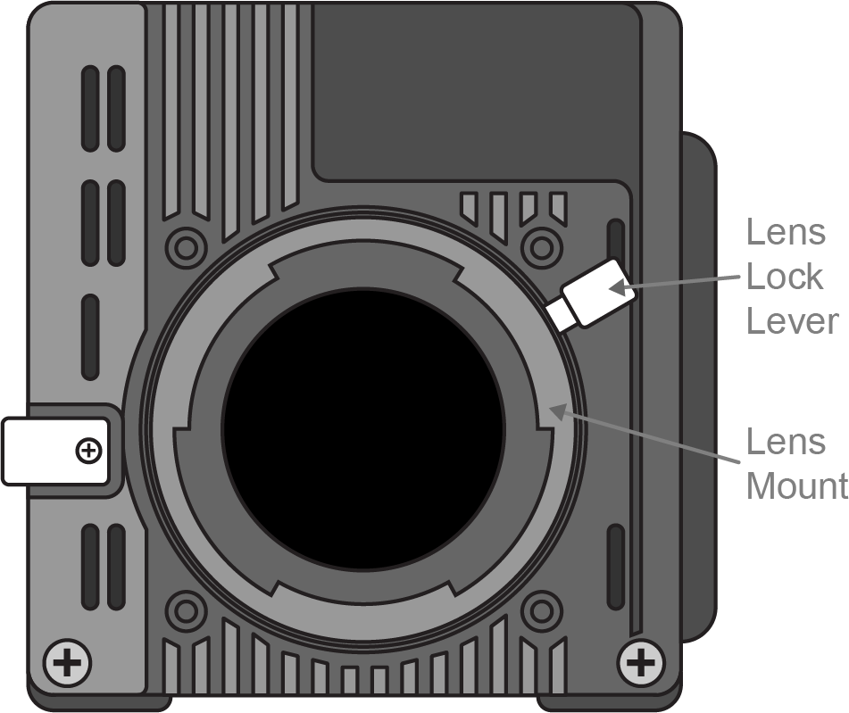
Figure: AC-H200-UCHR Back
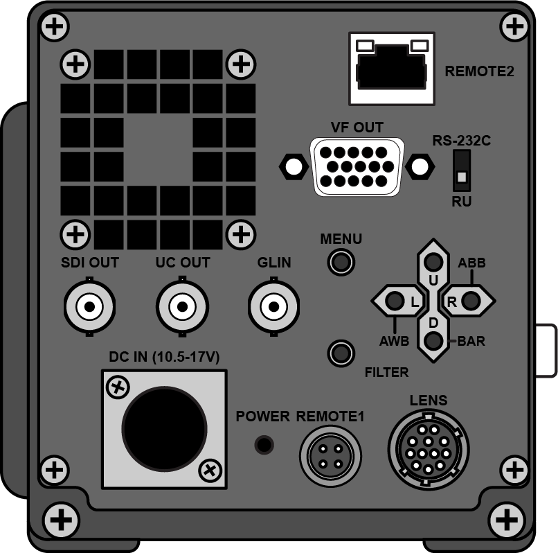
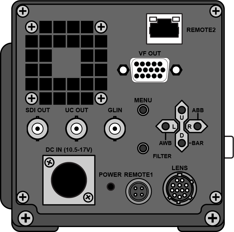
Figure: AC-Z50-UCHR Back
- Lens Mount — Standard bayonet type lens mount.
- Lens Lock Lever — Locks the lens onto the camera.
- SDI OUT — BNC for HD/SD-SDI video output. This is the main video output of the camera.
- UC OUT — BNC for UltraChromeHR signal.
- GL IN — BNC for Reference in. The camera accepts Tri-level or Black burst sync.
- DC IN — 4-Pin XLR for 12V DC power (10.5V to 17V) from external brick. Use only the external power supply provided with your camera.
- POWER — Power indicator shows that power is being provided to the camera (green).
- REMOTE1 — 4-Pin Multi connector for Remote Control Unit or direct serial control.
- LENS — 12-Pin Multi connector for lens control.
- FILTER — Button used to set filter control.
- D — Button used for menu navigation (down) or turn on Color bar signal output. Press the button when the menu is not active to turn on the color bars.
- R — Button used for menu navigation (right) or to turn on Automatic Black Balance Adjustment (ABB) if held for more than 2 seconds.
- U — Button used for menu navigation (up).
- L — Button used for menu navigation (left) or to turn on Automatic White Balance (AWB) if held for more than 2 seconds.
- MENU — Button used to access the menu system. The menu is shown on the SDI OUT or the VF OUT.
- VF OUT — DB15 connector for external viewfinder.
- REMOTE2 — RJ-45 connector for 10/100 BASE-T ethernet control.
- RS-232C / RU — Switch to set REMOTE1 connector for direct RS-232 serial control or control by a Remote Control Unit.