Network Architecture and Planning
The Sony Paint Control panel enables you to adjust lens iris, camera paint (shading), and other settings on supported Sony cameras. You can also save and load Sony scene files.
Camera Control System can be set up as a standalone paint control workstation, or can be integrated with a Ross Robotics robotic camera system and/or other Ross Video or third-party production solutions.
This Setup Guide describes how to install and configure the Sony Paint Control system as a standalone paint control workstation.
If you later purchase Ross Robotics, you can reconfigure your standalone Sony Paint Control system to integrate it with your Robotics system. For more information, contact Ross Video.
This section provides information about the Sony Paint Control system, to help you plan your installation. It includes the following topics:
- “Network Architecture”
- “System Components”
- “Planning the Workstation Components”
- “Planning the Studio and Network Components”
- “Hardware and Software Checklist”
Network Architecture
The Sony Paint Control system includes one or more paint control workstations, each with a camera control computer running DashBoard, which is a versatile control and monitoring interface for many Ross Video and openGear Partner devices. Through DashBoard you can access the Sony Paint Control panel, which is the camera control interface featuring camera iris and paint (shading) controls. Multiple cameras can be adjusted from a single workstation.
In systems with multiple workstations, an additional DashBoard computer acts as a proxy server. Camera control computers interact with the proxy server, which in turn interacts with cameras through Sony Camera Control Network Adapters (CNA-1). You can decide whether a given workstation controls some or all cameras. Any given camera can be controlled from one or more workstations.
This section of the Setup Guide describes network architecture options for a standalone paint control workstation. It includes the following topics:
- “RCP Mode and MSU Mode”
- “Network Architecture using CNA-1 Adapters in RCP Mode”
- “Network Architecture using CNA-1 Adapters in MSU Mode”
RCP M ode and MSU Mode
In Ross Video’s Sony Paint Control system, the Sony Paint Control panel sends commands to one or more CNA-1 adapters, which communicate with Sony cameras and control them. The CNA-1 adapters are configured to run either in Remote Control Panel (RCP) mode, or Master Setup Unit (MSU) mode:
-
RCP Mode — Each camera is associated with a dedicated CNA-1 Adapter. The camera control computers address each camera directly through the camera’s CNA-1 Adapter. RCP mode is sometimes referred to as Gateway mode.
-
MSU Mode — The system includes one or more CNA-1 adapters, upgraded to run in MSU mode (Sony upgrade HZC-MSCN1 ). Each CNA-1 adapter controls a group of cameras. For systems with a large number of cameras, deploying multiple CNA-1 adapters may improve response time, as the system queues control requests and polls the cameras for status updates. Additionally, a Sony MSU or a CNA-1 adapter is required to act as the master device on the Sony network.
MSU mode is also sometimes referred to as Multi-Camera mode.
noteIf you are using existing CNA-1 adapters for camera control, confirm that they can be upgraded to operate in MSU mode.
For several of the procedures in this manual, you need to know whether your system uses CNA-1 adapters in RCP mode or in MSU mode .
Mixed configurations are also supported, in which some CNA-1 Adapters operate in RCP mode, and others in MSU mode.
Network Architecture using CNA-1 Adapters in RCP Mode
Figure ?? shows the architecture of a Sony Paint Control system that includes three Sony cameras, any of which can be controlled from either of the two paint control workstations. In this example, the system uses CNA-1 units in RCP mode, with one CNA-1 unit per camera.
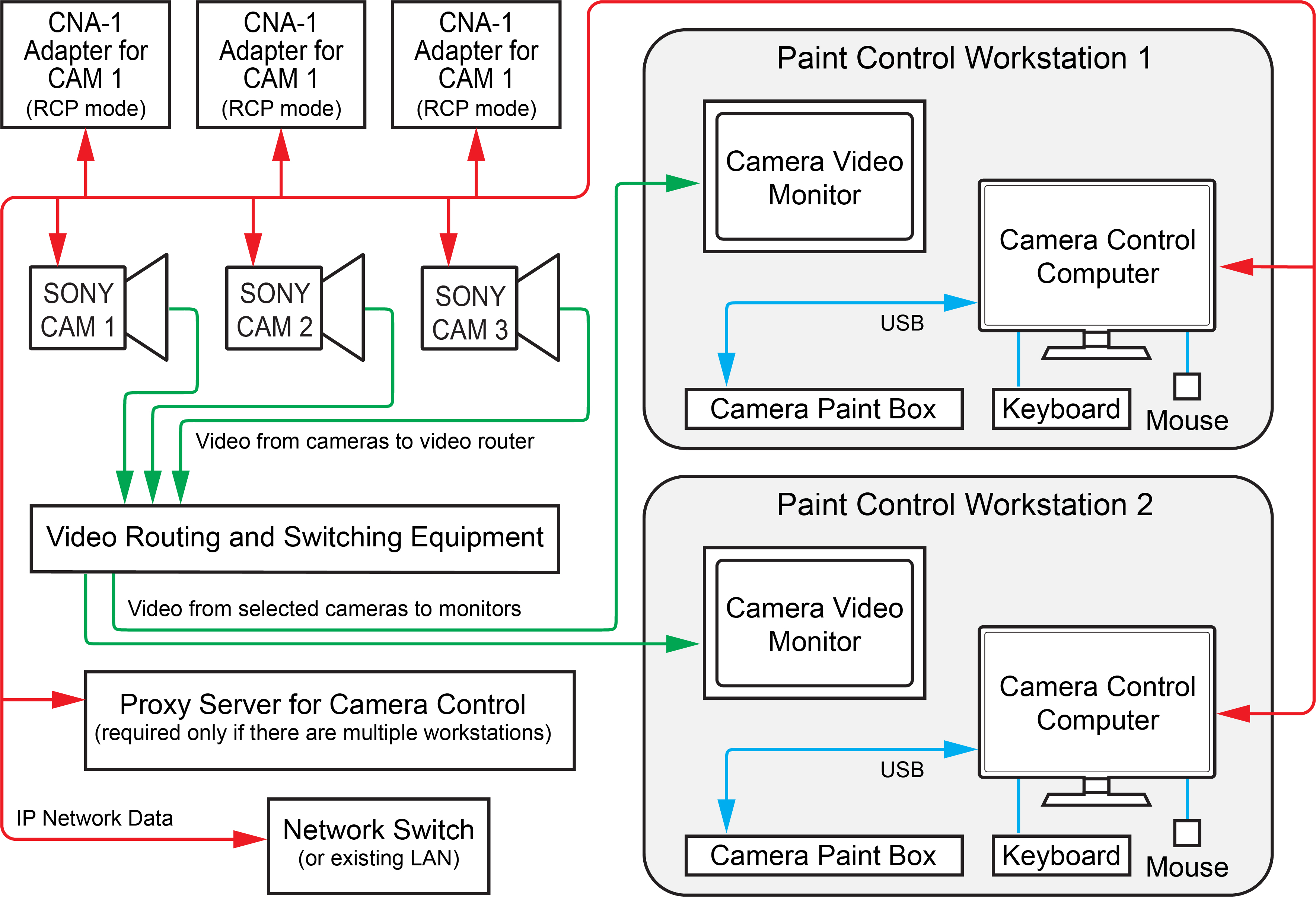
Figure 1 - - Camera Control System using CNA-1 Adapters in RCP Mode
All Sony cameras and CNA-1 adapters are assigned individual IP addresses on the network. Each CNA-1 adapter is configured with the IP address of the Sony camera it controls.
On the DashBoard computer acting as the proxy server, each camera is added as a device, using the IP address of the CNA-1 adapter that controls the camera.
Network Architecture using CNA-1 Adapters in MSU Mode
Figure ?? shows the architecture of a Sony Paint Control system that includes three Sony cameras, any of which can be controlled by either of the two paint control workstations.
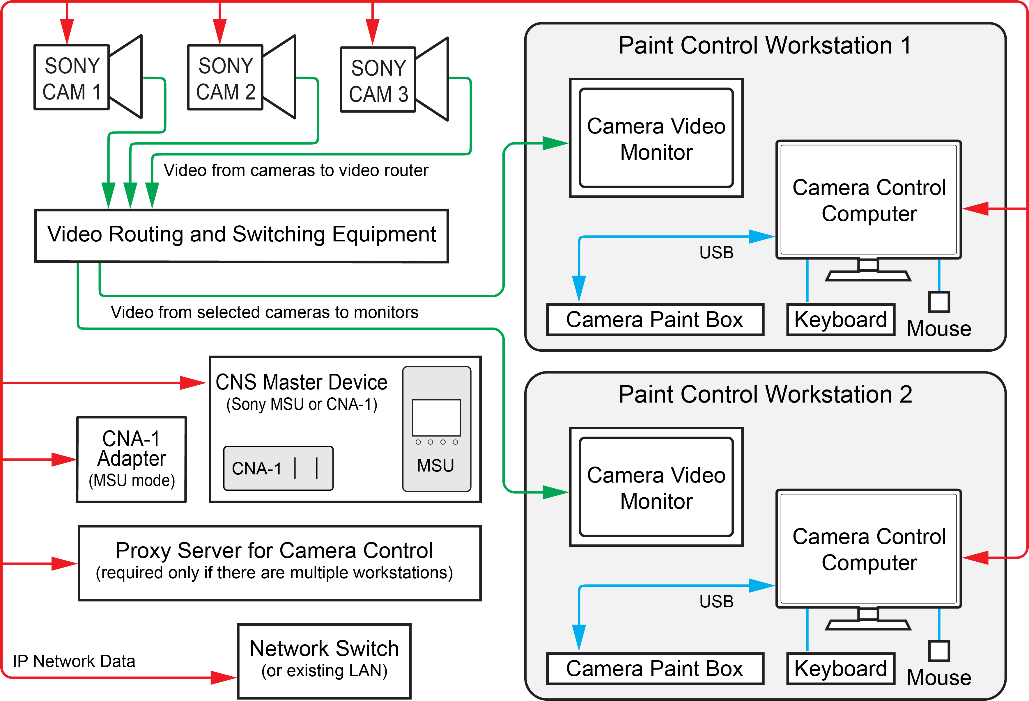
Figure 2 - - Camera Control System, using CNA-1 Adapters in MSU Mode
All Sony cameras and CNA-1 adapters are assigned individual IP addresses on the network. They are also assigned unique device numbers in the range 1 to 96.
On the DashBoard computer acting as the proxy server, each camera is added as a device, using the IP address of the CNA-1 adapter that controls the camera, and the camera’s device number.
An additional CNA-1 Adapter in MSU mode (or a Sony MSU), is required to establish a Sony Camera Network System (CNS) and co-ordinate control commands. A Sony CNS can accommodate up to 96 devices including cameras, CNA-1 adapters, and MSUs.
System Components
This section lists the components of a standalone Sony Paint Control system.
Workstation Components
The Sony Paint Control system includes one or more paint control workstations. Each workstation can control any or all cameras. Each workstation consists of the following:
-
Camera Control Computer — includes computer, monitor, keyboard, and mouse.
-
Camera Video Monitor — displays video from the camera being controlled, so you can monitor the effect of adjustments as you make them. The camera video monitor is not included.
-
Camera Paint Box (optional). The Camera Paint Box features physical knobs for adjusting iris and paint controls (gains and pedestals). These settings can also be controlled through the Sony Paint Control panel.
For more detailed information about the workstation components, see “Planning the Workstation Components”.
Studio and Network Components
Studio and network components include the following:
-
Network Switch — The system can use a dedicated network switch, or use an existing LAN.
-
Sony cameras — The system can control iris and paint functions on select Sony cameras.
-
Sony CNA-1 Camera Control Network Adapter(s) — CNA-1 adapters translate control commands to a protocol that Sony cameras can process. Depending on your system layout, there is either one CNA-1 adapter per camera, or one or more CNA-1 adapters that each control a group of cameras.
-
Sony Master Setup Unit (MSU) — In systems where a CNA-1 adapter controls multiple cameras, an additional CNA-1 adapter (or MSU) acts as the master device on the Sony network
-
Proxy server computer — In systems with multiple paint control workstations, the proxy server communicates with the cameras. All camera control requests from camera control computers are handled by the proxy server.
For more detailed information about the studio and network components, see “Planning the Studio and Network Components”.
Planning the Workstation Components
This section describes the components of a paint control workstation, to help you plan your installation.
The main topics in this section are as follows:
Camera Control Computer and Accessories
Each Camera Control Computer runs DashBoard, which is a versatile control and monitoring interface for many Ross Video and openGear Partner devices. Through DashBoard you can access the Sony Paint Control panel, which is the camera control interface featuring camera iris and paint (shading) controls.
You need one Camera Control Computer running DashBoard at each paint control workstation. DashBoard is free, but the Sony Paint Control panel is a licensed application. You require one license for each workstation.
You can purchase your Camera Control Computer(s) from Ross Video. Alternatively, you can use any computer that meets the Windows system requirements for installing DashBoard. To view the DashBoard system requirements, download the DashBoard User Guide at http://www.rossvideo.com/control-systems/dashboard/index.html.
All computers are connected to a single Ethernet IP network.
If your system includes multiple paint control workstations, the camera control computers are set up in a primary-secondary topology. On each camera control computer, DashBoard is configured to be a secondary instance. On an additional proxy server computer, DashBoard is configured to be the primary instance.
Camera Video Monitor
The camera video monitor displays video from the camera being controlled so you can monitor the effect of adjustments as you make them. The camera video monitor is usually a carefully calibrated reference monitor. Sometimes two identical monitors are used to compare video output of two cameras side-by-side. Video routing equipment is required to direct the desired video feed(s) to the monitor(s).
Camera video monitors and routing equipment operate independently of the Camera Control System. The Sony Paint Control panel and Camera Paint Box do not select video to be displayed on camera video monitors.
Camera video monitors and video routing equipment are not included as part of the Sony Paint Control system.
Camera Paint Box (optional)
The Camera Paint Box is an optional accessory that features physical knobs for adjusting iris and paint controls (gains and pedestals). These settings can also be controlled through the Sony Paint Control panel.
Each paint control workstation may or may not include a Camera Paint Box.
The Camera Paint Box is connected to the camera control computer by a USB cable. The Camera Paint Box is designed to occupy 1RU in a standard 19” component rack.
Planning the Studio and Network Components
This section describes the studio and network components of a Sony Paint Control system, to help you plan your installation.
The main topics in this section are as follows:
- “Cameras”
- “Sony CNA-1 Camera Control Network Adapters”
- “Proxy Server Computer”
- “Network Configuration”
Cameras
The Sony Paint Control system works with Sony broadcast video cameras that communicate via Sony 700PTP protocol. This includes Sony System 700 series cameras, and may include others. For information about which Sony cameras are supported, contact Ross Video.
Sony CNA-1 Camera Control Network Adapters
The Sony CNA-1 Camera Control Network Adapter translates Sony 700PTP control protocol to a protocol that the camera control system can process.
If your system uses CNA-1 adapters in RCP mode, each Sony camera requires a dedicated CNA-1 adapter.
If your system uses CNA-1 adapters in MSU mode, one or more CNA-1 adapters that have been upgraded to run in MSU mode (Sony upgrade HZC-MSCN1 ) are required. Each CNA-1 adapter controls a group of cameras. For systems with a large number of cameras, deploying multiple CNA-1 adapters may improve response time, as the system queues control requests and polls the cameras for status updates. An additional CNA-1 adapter (or MSU) acts as the master device on the Sony network.
The CNA-1 adapter(s) and MSU (if present) are connected to the same Ethernet IP network as the cameras and the camera control computer.
CNA-1 adapters are powered by Power over Ethernet (PoE). Your network must be PoE-capable. For information about power consumption, see the Operation Manual for the CNA-1 adapter.
Proxy Server Computer
If your system includes multiple paint control workstations, the camera control computers are set up in a client/server topology. On the proxy server, DashBoard is configured to be the 'proxy server' instance. On each camera control computer, DashBoard is configured to be a client of the proxy server instance.
The proxy server communicates with the cameras. All camera control requests from camera control computers are handled by the proxy server.
Because the proxy server must remain on at all times, we recommend you use a server-grade computer installed in a rack room. Alternatively, you can designate one of the camera control computers to act as the proxy server.
You can purchase a server from Ross Video. Alternatively, you can use any computer that meets the Windows system requirements for installing DashBoard. To view the DashBoard system requirements, download the DashBoard User Guide at http://www.rossvideo.com/control-systems/dashboard/index.html.
Network Configuration
Components of the Sony Paint Control system communicate over an Ethernet IP network. You can use a dedicated network switch or an existing network.
The following components require network connections:
- Each Camera Control Computer
- Each Sony camera
- Each Sony CNA-1 Camera Control Network Adapter and the Sony MSU (if present)
- The proxy server (only required for systems that have multiple paint control workstations)
Network cables between components are not included.
Hardware and Software Checklist
The tables in this section list components required for your system. You can use the tables as checklists when determining what you purchase.
Table 1 - Paint Control Workstation Equipment and Software
| Quantity | Item | Source | Notes / Requirements |
|---|---|---|---|
| Camera Control Computer Must include monitor, keyboard, and mouse. | Ross Video or Other | One computer per paint control workstation. Ross Video sells an all-in-one computer for this purpose. Computers must meet Windows system requirements for DashBoard installation. Computers require power supply outlets. | |
| Sony camera control license | Ross Video | One license per paint control workstation. | |
| Camera Paint Box | Ross Video | Maximum one per paint control workstation. Optional accessory. The Camera Paint Box requires a power supply outlet. | |
| Camera video monitor | Other | Minimum one per paint control workstation. Can have multiple monitors for side-by-side comparison of camera outputs. Monitors power supply outlets. | |
| Routing and switching equipment for camera video monitor(s) Must include video cabling between cameras and router, and between router and monitor(s). | Ross Video and/or Other | Independent of Camera Control System.. Typically, an existing video router is used. Ross Video can provide video routing solutions. Routing equipment requires power supply outlets. |
Table 2 - Studio and Network Equipment
| Quantity | Item | Source (Ross or Other) | Notes |
|---|---|---|---|
| Sony camera | Other | One or more. Contact Ross Video for information about which Sony cameras are supported. Each camera requires a power supply outlet. | |
| Sony CNA-1 Control Network Adapter | Other | If in RCP mode, one per Sony camera. If in MSU mode, one or more for camera control, plus one to act as the master device on the Sony network. Alternatively, a Sony MSU can act as the master device. Note: CNA-1 adapters are powered by Power over Ethernet (PoE). | |
| Sony software upgrade HZC-MSCN1 for Sony CNA-1 adapters, to enable them to run in MSU mode | Other | This applies only if your system uses Sony CNA-1 adapters in MSU mode. By default, CNA-1 adapters are not capable of operating in MSU mode. A software upgrade from Sony is required for each CNA-1 adapter. | |
| Proxy server for camera control | Ross Video or Other | Required if your system has multiple paint control workstations. Ross Video sells servers for this purpose Server must meet Windows system requirements for DashBoard installation. Server requires a power supply outlet. | |
| Camera control license for proxy server computer | Ross Video | License fees are based on the number of paint control workstations in your system. If your system has a proxy server running on a separate computer (as opposed to running on a camera control computer), the license for the proxy server computer is provided free of charge. | |
| Network Switch | Other | One required. Can use dedicated network switch, or an existing LAN. Must be PoE-capable to power Sony CNA-1 adapter(s) | |
| Ethernet network cables | Other | The following require network connections:
|