Install and Configure the System
This section describes how to install and configure a standalone Sony Paint Control system.
Components in the system communicate over an Ethernet network. All components in the system must use the same subnet mask and gateway. Determine the subnet mask and gateway in advance so you can configure the IP addresses of the components as you install them. If you plan to use an existing network, ask your network administrator to provide an available subnet mask and gateway.
Before you install the system, you need to plan the installation. For more information, see “Network Architecture and Planning”.
In Ross Video’s Sony Paint Control system , the Sony Paint Control panel sends commands to one or more CNA-1 adapters, which communicate with Sony cameras and control them. The CNA-1 adapters are configured to run either in Remote Control Panel (RCP) mode or Master Setup Unit (MSU) mode. Before you install and configure the system, you need to know which CNA-1 mode your system will use. For more information, see “RCP Mode and MSU Mode”.
Perform the installation procedures in the following order:
- “Establish an Ethernet Network”
- “Install Camera Control Computers”
- “Install Camera Paint Boxes”
- “Install the Proxy Server”
- “Install and Configure Sony Cameras”
- “Install and Configure Sony CNS Master Device (for MSU Mode)”
- “Install and Configure CNA-1 Network Adapters (for MSU Mode)”
- “Install and Configure CNA-1 Network Adapters (for RCP Mode)”
- “Install DashBoard Software on All Computers”
- “Configure the First Computer”
- “Configure Additional Camera Control Computers”
- “Configure the Camera Paint Box Connection”
- “Install the Video Monitor(s) and Routing/Switching Equipment”
Establish an Ethernet Network
Ross Video’s Sony Paint Control system can use a dedicated network switch, or use an existing LAN.
To set up a dedicated network switch:
- Install the network switch in an appropriate location.
- Connect the power supply for the switch.
- Turn on the switch.
Install Camera Control Computers
Each paint control workstation includes one camera control computer. This section describes how to install a camera control computer provided by Ross Video. If your computer is not provided by Ross Video, the steps may vary somewhat.
To install a Camera Control Computer and Peripherals:
-
Position the camera control computer in the paint control workstation location.
Ensure that the touch-screen monitor is within easy reach of the operator. Ensure that the optical drive, accessory ports, and buttons on the right and left edges of the computer are accessible.
-
Position the keyboard and mouse within easy reach of the operator, and then plug them into the connection panel on the back of the computer.
-
Plug one end of an Ethernet cable into the connection panel on the back of the computer. Connect the other end to the IP network.
-
Connect the power cable to the computer, and to a suitable power outlet.
-
Configure the networking parameters (IP address, subnet mask, and gateway).
Install Camera Paint Box es
The Camera Paint Box is an optional accessory. Each paint control workstation may or may not include a Camera Paint Box.
To install a Camera Paint Box :
-
Position the Camera Paint Box in the paint control workstation location.
Ensure that the Camera Paint Box is within easy reach of the operator.
The Camera Paint Box can sit on a flat surface, or occupy 1RU in a standard 19” component rack.
-
Plug one end of the provided USB cable into the Camera Paint Box. Plug the other end into a USB connector on the back of the camera control computer.
-
Plug the power cable into the Camera Paint Box, and into a suitable power outlet.
On the front of the Camera Paint Box, a green LED indicates that the unit is powered.
Install the Proxy Server
This section applies only if your system has multiple paint control workstations.
The proxy server communicates with the cameras on behalf of the camera control computers. It must always be running, and must be on the same network as the other components of the system.
This section describe how to set up a proxy server computer provided by Ross Video. If your computer is not provided by Ross Video, the steps may vary somewhat.
The operator does not need physical access to the proxy server. The server can be installed in a rack room. It does not need a dedicated keyboard and mouse. You can use a KVM or use Windows Remote Desktop to interact with the server.
To install the Proxy Server:
- Position and install the server in a standard 19” component rack.
- Connect the power cable to the computer, and to a suitable power outlet.
- Plug one end of an Ethernet cable into the server. Connect the other end to the IP network.
- Turn on the server.
- Configure the networking parameters (IP address, subnet mask, and gateway).
Install and Configure Sony Cameras
This section describes how to install Sony cameras, and how to set their communication protocol to RS-422.
To install and configure a camera:
-
Position and mount the camera.
-
Connect the camera to the Ethernet network.
-
On the camera, find the IRIS switch and set it to the automatic (A) position.
-
Plug the camera power supply unit into the camera and to a suitable power outlet.
-
Connect a video cable from the camera’s video output to a video monitor, and then turn on the video monitor so you see the camera output.
-
Using the camera’s on-screen configuration menu, do the following:
-
Set the IP address of the camera. Each camera must have a unique IP address.
Note the IP address you set. You will need to know the IP address of each camera for later procedures.
-
Set the CNS mode , as follows:
- If your system uses CNA-1 adapters in MSU mode , set the CNS Mode to MCS .
- If your system uses CNA-1 adapters in RCP mode , set the CNS Mode to Bridge .
-
If your system uses CNA-1 adapters in MSU mode , set a unique device number (1 - 96 ) and record it. You will need to know the device number of each camera for a later procedure.
tipEach device on the Sony Camera Network System (CNS), such as a camera, CNA-1 adapter, or MSU requires a unique device number.
tipFor more information about configuring your Sony camera, see the manual(s) that came with the camera.
-
-
Disconnect the video output cable from the video monitor, and then connect the video output to its intended destination.
Install and Configure Sony CNS Master Device (for MSU Mode)
When CNA-1 adapters are used in MSU mode , the Sony Camera Network System (CNS) requires an additional master device on the network. The master device can be either a Sony Master Setup Unit (MSU), or a CNA-1 adapter in Master mode.
Install and configure the master device to operate on the CNS network. For more information, consult Sony manuals that came with your device.
Install and Configure CNA-1 Network Adapters (for MSU Mode)
This procedure applies only if your system uses CNA-1 adapters in MSU mode . If your system uses CNA-1 adapters in RCP mode , skip this procedure.
The system includes one or more CNA-1 adapters. Each CNA-1 adapter controls a group of cameras. For systems with a large number of cameras, deploying multiple CNA-1 adapters may improve response time, as the system queues control requests and polls the cameras for status updates.
The Sony Camera Control Network Adapter (CNA-1) translates between Sony Proprietary Protocol (SPP or 700PTP), which is used by Sony cameras, and Sony Simple Camera Protocol (SSCP), which is designed to enable non-Sony controllers and cameras to connect to a Sony Camera Network System (CNS).
By default, CNA-1 adapters are not capable of operating in MSU mode. A special software upgrade (HZC-MSCN1 ) from Sony is required for each CNA-1 adapter. Upgrade each CNA-1 adapter before performing the steps in this section.
Configure each CNA-1 adapter as follows:
-
In a web browser, type the IP address of the CNA-1 adapter in the address bar and then press Enter .
The CNA-1 configuration menu appears.
tipThe factory default IP address is 192.168.1.1 . A user name and password may be required to access portions of the configuration menu.
-
On the System tab, specify IP Configuratio n settings to assign a unique IP address for the CNA-1 adapter.
The IP Address and Subnet Mask must be accessible by all computers in the system.
Note the IP address you assigned. You will need it when you later register cameras.
-
On the CNS tab , specify CNS Configuration settings as follows:
-
Set CNS Mode to MCS .
-
Disable Master Mode .
-
Set the Master IP Address to the IP address of the CNA-1 adapter or MSU that is the master device on the SONY CNS network.
-
Set a unique device number (Device No. ) for the CNA-1 adapter (1 - 96 ).
tipEach device on the Sony Camera Network System (CNS), such as a camera, CNA-1 adapter, or MSU requires a unique device number.
-
-
On the CNS tab , specify Gateway Configuration settings as follows:
- Set Gateway Mode to Enable .
- Set Emulation Mode to MSU .
-
Tap Apply .
Install and Configure CNA-1 Network Adapters (for RCP Mode)
This procedure applies only if your system uses CNA-1 adapters in RCP mode . If your system uses CNA-1 adapters in MSU mode , skip this procedure.
The Sony Camera Control Network Adapter (CNA-1) translates between Sony Proprietary Protocol (SPP or 700PTP), which is used by Sony cameras, and Sony Simple Camera Protocol (SSCP), which is designed to enable non-Sony controllers and cameras to connect to a Sony Camera Network System (CNS).
Because your system uses CNA-1 adapters in RCP mode, each Sony camera must be associated with its own CNA-1 adapter. Cameras and CNA-1 adapters do not have to be co-located. They must all reside on the same IP network.
Configure each CNA-1 adapter as follows:
-
In a web browser, type the IP address of the CNA-1 adapter in the address bar and then press Enter .
The CNA-1 configuration menu appears.
tipThe factory default IP address is 192.168.1.1 . A user name and password may be required to access portions of the configuration menu.
-
On the System tab, specify IP Configuratio n settings to assign a unique IP address for the CNA-1 adapter.
The IP Address and Subnet Mask must be accessible by all computers in the system.
Note the IP address you assigned. You will need it when you later register cameras.
-
On the CNS tab , specify CNS Configuration settings as follows:
- Set CNS Mode to Bridge .
- Set Target IP Address to the actual IP address of the associated camera.
-
On the CNS tab , specify Gateway Configuration settings as follows:
- Set Gateway Mode to Enable .
- Set Emulation Mode to RCP .
-
Tap Apply .
Install DashBoard Software on All Computers
Install the latest version of DashBoard on each Camera Control Computer and on the proxy server (if present).
DashBoard and the DashBoard User Guide are available as free downloads from Ross Video. The DashBoard User Guide contains instructions for installing DashBoard. Both are available at the following location:
http://www.rossvideo.com/control-systems/dashboard/index.html.
The steps for configuring the first computer in the Camera Control System are different than the steps for subsequent computers:
- If your system includes only one paint control workstation, the camera control computer is the first (and only) computer.
- If your system includes multiple paint control workstations, the proxy server is the first computer.
To configure the first computer, you perform the following tasks:
To perform the steps in this section, you need to have good working knowledge of basic computer networking procedures.
DashBoard is free, but use of the Vision[Ai]ry panel requires one license per computer.
DashBoard supports two licensing options: Software-Based Licensing and Ross Key Based Licensing .
Software-based licensing involves connection of DashBoard to the Ross activation server either directly or via a Ross Product Manager licensing server. To use software-based licensing, you will need a product key provided by Ross.
Ross Key Based Licensing is a fixed license tied to your hardware. During the licensing process you will need to send a key code to Ross technical support who will return a license key for you to enter into DashBoard.
For more information, refer to the DashBoard User Guide 8351DR-004-XX .
Configure Network Settings
To configure network settings:
-
Configure the network settings on the computer so it can communicate with the CNA-1 adapter(s).
If this computer is the proxy server, note its IP address. You will need to know the proxy server’s IP address for later procedures.
Add Cameras
Add cameras to the first computer only. If there are multiple paint control workstations, the first computer is the proxy server, and the other workstations access the cameras through the proxy server.
Add the cameras in the order in which you want them to appear when listed in the Sony Paint Control panel .
To add a camera:
-
On the first computer, open DashBoard.
-
From the File menu, tap New , and then tap Other .
The New dialog box appears.
-
Expand the Camera Control node, tap Sony Camera , and then tap Next .
The New Ross Video Sony Camera Connection dialog appears.
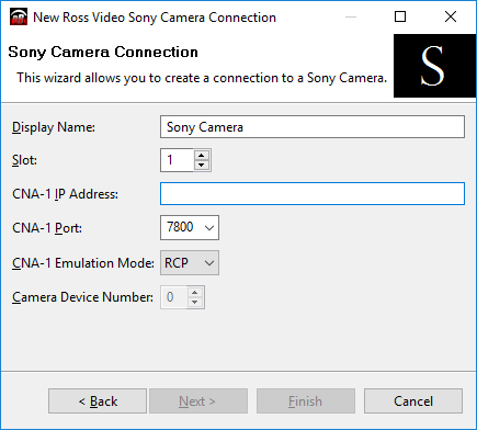
Figure 1
-
In the Display Name box, type a name for the camera. This name will appear in the DashBoard component tree.
-
In the CNA-1 IP Address box, type the IP address of the CNA-1 adapter that controls the camera you want to add.
-
In the CNA-1 Port box, type the port number for the CNA-1 adapter that controls the camera you want to add.
tipThe default port number is 7800 . Do not change this value unless you configured a different port number on the CNA-1 adapter.
-
In the CNA-1 Emulation Mode list, do one of the following:
- If your system uses CNA-1 adapters in RCP mode , select RCP .
- If your system uses CNA-1 adapters in MSU mode , select MSU .
-
If your system uses CNA-1 adapters in MSU mode , in the Camera Device Number list, specify the device number you assigned to the camera when you configured it.
-
Tap Finish .
-
In the DashBoard Component Tree , expand the Sony Cameras node.
-
Tap and hold, and then release the Slot node for the camera you just added, and then tap Share Device .
-
Expand the Slot node for the camera you just added.
-
Tap Remote Control .
-
If the Sony Paint Control panel appears, go to step 9.
-
When you add the first camera to DashBoard, you will need to apply a license.
The remote control page will show a warning message:

Figure 2
To apply a software-based license
-
From the main toolbar, select Window > Preferences . Refer to Figure ??.
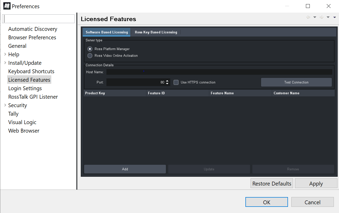
Figure 3 - DashBoard Licensed Features - Software Based Licensing tab
-
The Preferences dialog box opens.
-
From the Preferences dialog box, select Licensed Features .
-
In the Licensed Features dialog box, ensure the Software Based License tab is selected.
-
Select the Server type that you are using to provide licensing.
-
If you are using the Ross Platform Manager server type, enter the Host Name and Port of the server and whether to Use HTTPS connection .
Note: Select Apply to save your server settings.
Note: Use the Test Connection button to confirm a successful connection if necessary. -
Once connection to the server is established, select Add and enter the product key provided to you.
If successful, the feature you added will appear in the Licensed Features table.
Note: Select Apply to confirm your changes.To apply a Ross key based license
For obtaining and entering a Ross licensing key code, complete the following: -
From the main toolbar, select Window > Preferences . Refer to Figure ??.
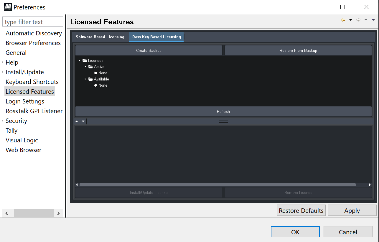
Figure 4 - DashBoard Licensed Features - Ross Key Based Licensing tab
-
The Preferences dialog box opens.
-
From the Preferences dialog box, select Licensed Features .
-
In the Licensed Features dialog box, ensure the Ross Key Based License tab is selected.
-
From either the Active or Available subfolder, select the feature you want to update.
-
To obtain a Ross License Key by completing the following:
Click Install/Update License .
ii. The Enter License Key dialog box opens. Refer to Figure ??.
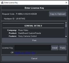
Figure 5 - DashBoard Licensed Features - Enter License Key
-
iii. Select Copy to Clipboard to copy your request code.
iv. Paste the request code into an e-mail to Ross Video (techsupport@rossvideo.com), requesting a corresponding license key. Be sure to include the original Ross Video sales order number.
cautionDo not close the Enter License Key dialog box until you receive and apply an activation code from Ross Video. If you leave the Enter License Key dialog box, the activation code you receive will not work. It is valid only for the session during which it was generated.
When you receive the license key via email, copy and paste it into the License Key box, and then tap Install.
vi. The selected feature updates and the most current data is displayed in the License Details .
-
In DashBoard, close the Sony Cameras - Slot x tab .
-
In the Component Tree , tap Remote Control .
The Camera Control Panel appears.
-
In the camera selection area at the top of the panel, tap the camera name.If the camera initializes and connects, it has been successfully added and can be controlled.
-
If the camera fails to appear in the DashBoard tree, or appears with a red dot, do the following:
- Ensure that power is connected to the camera, and that the cameras is turned ON .
- Check the IP address you typed in Step 4 a nd ensure that it matches the IP address of the camera.
-
Manage Cameras (CNA-1 Configuration)
The Sony Paint Control panel features a restricted-access interface for viewing the status of camera and CNA-1 connections, and for managing advanced configuration settings.
The configuration interface is always available from the first computer (proxy server). You can also make it available to other paint control workstations.
To share the advanced configuration interface to all workstations:
- In the DashBoard component tree, expand the node for the cameras, expand the Sony Camera Server node (Slot 0 ), press and hold the Master Control node, and then tap Share Device (Figure ??).
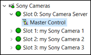
Figure 6 - - The Master Control Node in the DashBoard Tree
To access the advanced configuration interface:
-
Do one of the following:
-
If you are configuring the first (proxy server) computer, tap the Manage Cameras button.
The advanced configuration interface appears (Sony CNA-1 Configuration ). See Figure 5 -.
-
If you are configuring a computer other than the first computer (proxy server), in the DashBoard tree, expand the node for the cameras, expand the Sony Camera Server node (Slot 0 ), and then tap the Master Control node (Figure 5 -).
Figure 7
Figure 5 - - The Master Control Node in the DashBoard Tree
-
The advanced configuration interface appears (Sony CNA-1 Configuration ). See Figure ??.
tipIf the DashBoard Tree does not have a Master Control node, the configuration settings are not available to you. Contact your administrator.
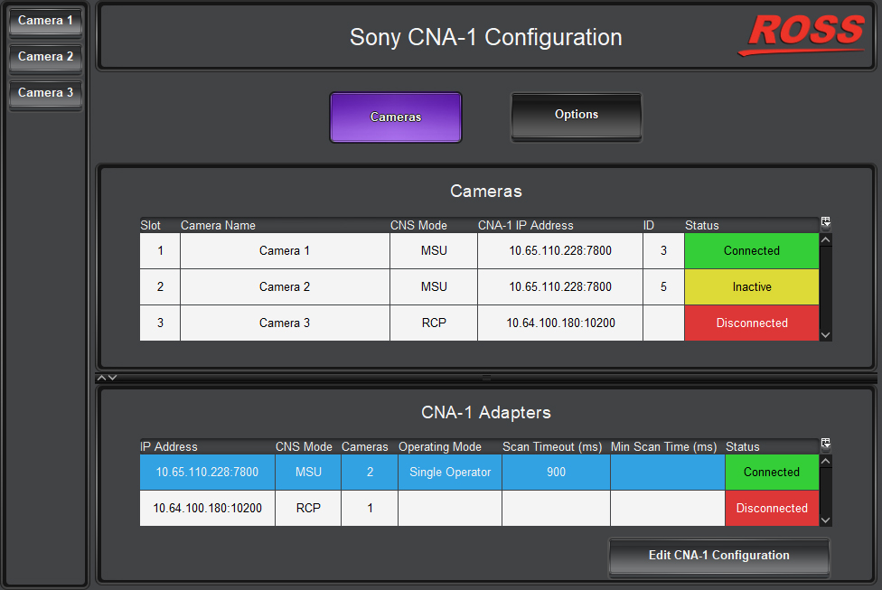
Figure 8 - - The Advanced Configuration Interface (Sony CNA-1 Configuration)
- Tip : To exit the advanced configuration interface and return to camera operation, tap a camera button.
To view the status of camera and CNA-1 connections:
-
In the Sony Paint Control panel , tap the Cameras button.
The Cameras list and the CNA-1 Adapters list appear.
To edit CNA-1 configuration (applies only to CNA-1 adapters running in MSU mode)
-
In the Sony Paint Control panel , tap the Cameras button,
-
In the CNA Adapters list, tap the adapter you want to edit.
-
Tap the Edit CNA-1 Configuration button.
The CNA-1 Configuration dialog box appears (Figure ??).
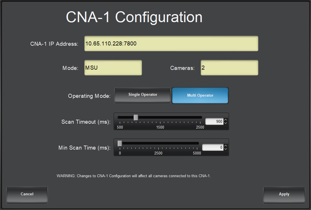
Figure 9 - - CNA-1 Configuration Dialog Box
-
Observe the CNA-1 IP address , CNS Emulation Mode , and the number of Cameras connected to the CNA-1.
These properties are not editable in DashBoard. They are configured on the CNA-1 adapter.
-
Specify the Operating Mode :
- Single Operator — Select this option if your system has only one paint control workstation.
- Multi Operator — Select this option if your system has multiple paint control workstations.
tipThe selected option has a blue background.
-
Set the Scan Timeout , in milliseconds (ms).
When the system switches to point to a new camera, it sends queries to retrieve updated parameter data. The Scan Timeout setting specifies how long the system waits to receive that data before declaring a Scan Timeout error and possibly moving on to query the next camera.
If the Scan Timeout value is too low, some relevant data may not be collected in time.
If the Scan Timeout value is too high, the updating of parameters as shown in the Sony Paint Control panel may lag, especially if there are many cameras.
noteThe default value for Scan Timeout (900 ms) is suitable for most systems. We recommend you do not change it unless instructed to do so by Ross Video Technical Support.
-
Set the minimum scan time (Min Scan Time ), in milliseconds (ms).
This setting is available only if the Operation Mode is set to Multi Operator .
The system queries each camera one by one to retrieve updated parameter data. The Min Scan Time setting specifies the minimum amount of time the system lingers after querying a given camera before it proceeds to the next camera.
If the Min Scan Time value is too low, the cameras are queried more often than necessary and more network traffic is generated. This is especially true in systems with few cameras.
If the Min Scan Time value is too high, the updating of parameters as shown in the Sony Paint Control panel may lag, especially if there are many cameras. This is especially true in systems with many cameras.
noteThe default value for Min Scan Time (0 ms) is suitable for most systems. We recommend you do not change it unless instructed to do so by Ross Video Technical Support.
To configure Sony Paint Control panel options:
-
In the Sony Paint Control panel , tap the Options button.
Camera Options settings appear (Figure ??).
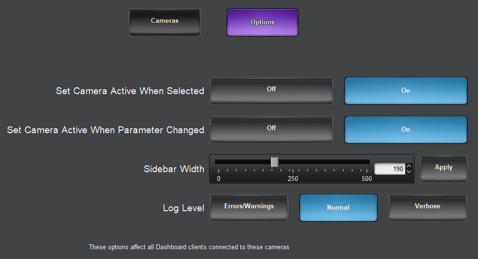
Figure 10 - - Camera Options
-
The options described in this step apply to systems that have Operator Mode set to Single Operator (see step 5).
A CNA-1 adapter establishes a direct control path to only one camera at a time (the active camera).
Commands are sent to cameras immediately, but updates can only be received from the active camera. This means that any changes applied outside of the DashBoard system, for example by automatic Iris or by an operator using a Sony RCP, will not be updated in the DashBoard UI until the camera becomes active.
You can control whether certain actions causes the CNA-1 adapter to switch its camera control path to the selected camera.
Configure the following options:
-
Set Camera Active When Selected — When On , selecting a camera causes the CNA-1 adapter to establish a direct control path to the selected camera. This applies to all selections made, whether through the Sony Paint Control panel or by other means.
importantThis setting applies to systems that use the DashBoard Selector Service , which controls how cameras are selected by various devices or systems. It works only if the cameras have been added to the Selection Mapping list in DashBoard. The Selection Mapping list is available through the DashBoard tree (DashBoard Services > Selector UI Mappings ).
-
Set Camera Active When Parameter Changed — When On , changing any parameter on a camera causes the CNA-1 adapter to establish a direct control path to that camera. This applies when parameters are changed through the Sony Paint Control panel .
-
-
Configure the following options:
- Sidebar Width — Sets the width of the camera list. Move the slider or specify a value, and then tap Apply .
- Log Level — Controls the level of detail presented in system activity logs. More intensive logging consumes CPU capacity and results in more logging data. The default setting is Normal . There is no need to adjust the logging level unless requested to do so by Ross Video.
Configure Additional Camera Control Computers
This section applies only if your system has multiple paint control workstations.
To perform the steps in this section, you need to have good working knowledge of basic computer networking procedures.
To configure an additional camera control computer:
-
Configure the network settings on the computer so it can communicate with the CNA-1 adapter(s) through the first (proxy server) computer.
-
Open DashBoard.
-
From the File menu, tap New , and then tap New TCP/IP DashBoard Connect or openGear Device .
The TCP/IP DashBoard Connect/openGear Device dialog box appears.
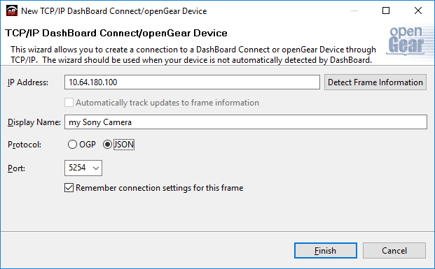
Figure 11 - - Connecting to the Proxy Server
-
In the IP Address box, type the IP address of the proxy server.
-
In the Display Name box, type a name for the camera node, as you want it to appear in the DashBoard component tree.
-
Select the JSON protocol.
-
In the Port box, type 5254 .
-
Tap Finish .
-
In the DashBoard Component Tree , expand the Sony Cameras node.
-
Expand the Slot node for the camera you just added.
-
Tap Remote Control .
-
If the Sony Paint Control panel appears, go to step 16.
-
When you add the first camera to DashBoard, you will need to apply a license.
The remote control page will show a warning message:Figure 12
-
In DashBoard, close the Sony Cameras - Slot x tab .
-
In the Component Tree , tap Remote Control .
The Camera Control Panel appears.
-
In the camera selection area at the top of the panel, tap the camera name.
If the camera initializes and connects, it has been successfully added and can be controlled.
-
Configure the DashBoard Selector Service , which controls how cameras are selected by various devices or systems. The selector service enables devices outside of DashBoard, such as a joystick panel or Sony RCP to select cameras. It works only if the cameras have been added to the Selection Mapping list in DashBoard. The Selection Mapping list is available through the DashBoard tree (DashBoard Services > Selector UI Mappings ).
Configure the Camera Paint Box Connection
Each camera paint box is connected to a camera control computer via a USB cable. You must configure the computer to interact with the Camera Paint Box.
DashBoard communicates with the Camera Paint Box through a service called the bridge server. To establish communication with the Camera Paint Box, you must:
- Install the bridge server software.
- Add and configure a DashBoard gateway for the Camera Paint Box.
To install the bridge server software:
-
Obtain the Bridge Server software zip file from Ross Video, and save it on the camera control computer.
-
Unzip the file to C:\Ross.
-
Open a command prompt window as Administrator , and change directory to the location where you unzipped the file, for example:
cd "C:\Ross\Bridge Server 4.5.0.4093"
-
Type the command to install the ManagedServicesHost.exe file and then press Enter . An example of the command is as follows:
C:> "Ross\Bridge Server 4.5.0.4093\ManagedServicesHost.exe" -install
-
Press Enter .
The Bridge Server software is installed. A message in the command prompt window appears when the installation is complete.
-
Close the command prompt window.
-
In a web browser, navigate to the Bridge Server configuration page at localhost:3000 .
-
If the PaintBox Bridge service is not running, tap Start .
tipFrom the configuration page, you can start or stop the server. Alternatively, you can start or stop the Bridge Service Host from the Services tab in Windows Task Manager .
To add and configure a DashBoard gateway for the Camera Paint Box
-
In DashBoard, from the File menu, tap New , and then tap TCP/IP DashBoard Connect or openGear Device .
The New TCP openGear Frame Connection dialog box appears.
-
In the IP Address box, type the IP address of the computer, or type localhost.
-
In the Display Name box, type a name for the node as you want it to appear in the DashBoard component tree, for example, Robotics DashBoard Gateway .
-
Select the JSON protocol.
-
In the Port box, type 5257 .
-
Select the Remember connection settings for this frame check box.
-
Tap Finish .
A new gateway node with the name you specified appears in the DashBoard component tree.
tipAfter you complete this procedure, you can expand the gateway node and tap Station 1 to open an interface that displays real-time data received from the Camera Paint Box .
-
In the DashBoard component tree, expand the DashBoard Services node.
-
Tap Device Class Mappings .
-
For each Class , in the Selected Device list, select the only available option in the list.
-
In the DashBoard component tree, tap Selector UI Mappings .
-
Set the Autowire Follows UI setting to ON .
Install the Video Monitor(s) and Routing/Switching Equipment
Each paint control workstation requires at least one video monitor to view camera output. The monitor enables you to monitor the effect of iris and paint adjustments as you make them. Sometimes two monitors are used, to compare video output of two cameras side-by-side.
Video routing/switching equipment is required to select the video. Ideally, the camera control operator should be able to switch the video from the paint control workstation.
The video monitor and routing equipment operate independent of the Camera Control System. The Sony Paint Control panel and Camera Paint Box do not select video to be displayed on the camera video monitor.
The video monitor and video routing equipment are not included as part of the Sony Paint Control system.
To install the Camera Video Monitor(s) and Video Routing/Switching Equipment
- Install the Video Routing / Switching Equipment.
- Install the video monitor(s) in the paint control workstation(s).
- Connect video cables between the camera video monitors and outputs on the routing/switching equipment.
- Connect video cables from each camera to an input on the routing/switching equipment.
- Configure the video routing/switching equipment so it is possible to route video from each camera to each camera video monitor.