System Overview and Planning
This section provides information about the Panasonic Camera Control System that can help you plan your installation. It contains the following topics:
- “System Overview”
- “Planning the Workstation Components”
- “Planning the Studio and Network Components”
- “Hardware and Software Checklist”
System Overview
The Panasonic Camera Control System enables you to adjust lens iris, camera paint (shading), and all camera menu settings for supported Panasonic cameras. It can be set up as a standalone camera control system, or integrated with a Ross Robotics robotic camera system.
This Setup Guide describes how to install and configure the Panasonic Camera Control System as a standalone camera control system.
This section lists the components of the system, and includes a system architecture diagram.
Workstation Components
The Panasonic Camera Control System includes one or more camera control workstations. Each workstation can control all cameras. Each workstation consists of the following:
-
A Camera Control Computer, monitor, keyboard, and mouse.
-
A Camera Video Monitor. This monitor (not included) displays video from the camera being controlled, so you can see on-screen menus and monitor the effect of adjustments as you make them.
-
A Camera Paint Box (Optional). The Camera Paint Box features physical knobs for adjusting iris and paint controls (gains and pedestals). These settings can also be controlled through the Camera Paint Control panel.
For more detailed information about the workstation components, see “Planning the Workstation Components”.
Studio and Network Components
Studio and network components include the following:
-
Network Switch. The system can use a dedicated network switch, or use an existing LAN.
-
Panasonic cameras. The system can control iris and paint functions on select Panasonic cameras.
-
Serial to Ethernet Converter. These units convert RS-422 signal from the camera to Ethernet communication.
-
Proxy server computer. In systems with multiple camera control workstations, the proxy server communicates with the cameras. All camera control requests from camera control computers are handled by the proxy server.
For more detailed information about the studio and network components, see “Planning the Studio and Network Components”.
System Architecture Diagram
Figure ?? shows the architecture of a Panasonic Camera Control System that includes six cameras in two studios. There are two camera control workstations. Each workstation includes an optional Camera Paint Box. Each studio has a serial-to-Ethernet converter (Comtrol unit) that can host up to four cameras. The Comtrol unit connects to the Ethernet network, and eliminates the need to run individual serial cables from each camera to the proxy server in the rack room.
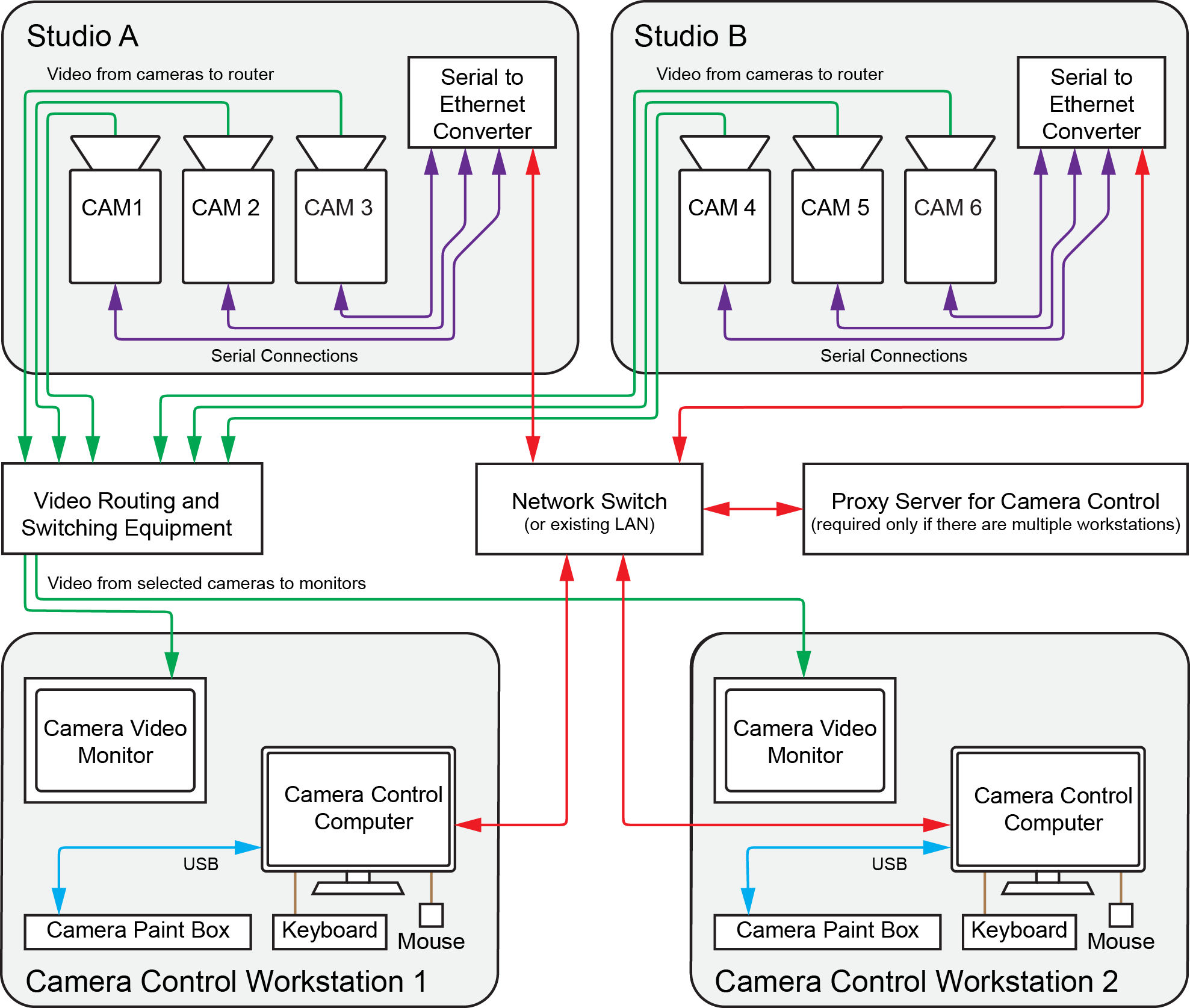
Figure 1 - - Architecture of a Standalone Panasonic Camera Control System (an example)
Planning the Workstation Components
This section describes the components of a camera control workstation, to help you plan your installation.
The main topics in this section are as follows:
Camera Control Computer and Accessories
The Camera Control Computer runs DashBoard, which is a versatile control and monitoring interface for many Ross Video and openGear Partner devices. Through DashBoard you can access the Camera Control panel, which is the camera control interface featuring camera iris and paint (shading) controls. The Camera Control panel also provides access to on-screen camera configuration menus.
You need one Camera Control Computer running DashBoard at each camera control workstation. DashBoard is free, but the Panasonic Camera Control System is a licensed application. You require one license for each camera control workstation.
You can purchase your Camera Control Computer(s) from Ross Video. Alternatively, you can use any computer that meets the Windows system requirements for installing DashBoard. To view the DashBoard system requirements, download the DashBoard User Guide at http://www.rossvideo.com/control-systems/dashboard/index.html.
If your system includes multiple camera control workstations, the camera control computers are set up in a primary-secondary topology. On each camera control computer, DashBoard is configured to be a secondary instance. On an additional proxy server computer, DashBoard is configured to be the primary instance.
Camera Video Monitor
The camera video monitor can display video from the camera being controlled, so you can see on-screen menus and monitor the effect of adjustments as you make them. The camera video monitor is usually a carefully calibrated reference monitor. Sometimes two monitors are used, to compare video output of two cameras side-by-side. Video routing equipment is required to direct the desired video feed to the monitor(s).
Camera video monitors and routing equipment operate independent of the Camera Control System. The Camera Control panel and Camera Paint Box do not select video to be displayed on camera video monitors.
When adjusting paint controls, technicians often use a waveform/vectorscope to fine-tune the properties of the camera output. The Camera Control Panel enables you to access the camera’s color bars output for calibration purposes.
Camera video monitors, video routing equipment, and waveforms/vectorscopes are not included as part of the Panasonic Camera Control System.
Camera Paint Box (optional)
The Camera Paint Box is an optional accessory that features physical knobs for adjusting iris and paint controls (gains and pedestals). These settings can also be controlled through the Camera Paint Control panel.
Each camera control workstation may or may not include a Camera Paint Box.
The Camera Paint Box is connected to the camera control computer by a USB cable. The Camera Paint Box is designed to occupy 1RU in a standard 19” component rack.
Planning the Studio and Network Components
This section describes the studio and network components of a camera control workstation, to help you plan your installation.
The main topics in this section are as follows:
Cameras
The Panasonic Camera Control System works with Panasonic AK-HC1500 video cameras, and may work with other Panasonic cameras that communicate over RS-422 serial protocol. For information about which Panasonic cameras are supported, contact Ross Video.
Serial to Ethernet Converter(s)
Supported Panasonic cameras communicate over RS-422 protocol. Serial to Ethernet converters enable the camera to communicate with other components of the Camera Control System.
The Camera Control System uses the Comtrol DeviceMaster RTS 4-Port DB9 four-port device server as a serial to Ethernet converter. The Comtrol unit is available from Ross Video.
The number of Comtrol units required depends on the number of cameras to be controlled, and their locations. Each Comtrol unit can host up to four cameras. Comtrol units are typically located close to the cameras, to reduce cable runs.
For example, if there are a total of six cameras split evenly between two studios, you would typically install one Comtrol unit in each studio, as shown in the “System Architecture Diagram”.
Serial Cables Between Cameras and Comtrol Units
Each camera connects to a Comtrol unit through a serial cable assembly. Because the required length of the cable assembly varies for each camera installation, each cable assembly is custom-made.
For each camera, you can make your own cable assembly end-to-end, or buy a set of two adapter cables from Ross Video and then make a custom-length cable to span between them (Figure ??).
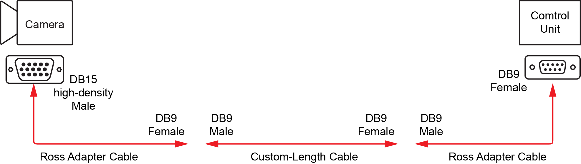
Figure 2 - - Serial Cable Assembly Made With Ross Adapter Cables
If you use a set of two Ross Video adapter cables, you must use both cable adapters. You cannot use only the cable adapter that attaches to the camera, because the cable pinouts will not be correct.
For the custom-length cable that spans between the two adapter cables, only pins 1 to 5 are used.
To manufacture an end-to-end cable assembly without Ross Video adapter cables, the pinout information is as follows:
Table 1 - Pinouts for Custom End-to-End Serial Cable Assembly
| Camera End Female DB9 | Comtrol End Male DB15 (high density) |
|---|---|
| Pin 4 | Pin 2 |
| Pin 5 | Pin 3 |
| Pin 10 | Pin 7 |
| Pin 9 | Pin 8 |
| Pins 11, 12,13,14,15 | SHELL |
When using robotic camera systems, make sure all cable assemblies are long enough to accommodate the full range of camera motion.
Proxy Server Computer
If your system includes multiple camera control workstations, the camera control computers are set up in a client/server topology. On the proxy server, DashBoard is configured to be the 'proxy server' instance. On each camera control computer, DashBoard is configured to be a client of the proxy server instance.
The proxy server communicates with the cameras. All camera control requests from camera control computers are handled by the proxy server.
Because the proxy server must remain on at all times, we recommend you use a server-grade computer installed in a rack room. Alternatively, you can designate one of the camera control computers to act as the proxy server.
You can purchase a server from Ross Video. Alternatively, you can use any computer that meets the Windows system requirements for installing DashBoard. To view the DashBoard system requirements, download the DashBoard User Guide at http://www.rossvideo.com/control-systems/dashboard/index.html.
Network Configuration
Components of the Panasonic Camera Control System communicate over an Ethernet network. You can use a dedicated network switch, or an existing network.
The following components require Ethernet network connections:
- Each Camera Control Computer
- Each Comtrol unit
- The proxy server (only required for systems that have multiple camera control workstations)
Ethernet cables between components are not included.
Hardware and Software Checklist
The tables in this section list everything you need to purchase for your system. You can use them as checklists when determining what you need.
Table 2 - Camera Control Workstation Equipment and Software
| Quantity | Item | Source | Notes / Requirements |
|---|---|---|---|
| Camera Control Computer Must include monitor, keyboard, and mouse. | One computer per workstation. Ross Video sells an all-in-one computer for this purpose. Computers must meet Windows system requirements for DashBoard installation. Computers require power supply outlets. | ||
| Panasonic camera control license | Ross Video | One license per camera control workstation. | |
| Camera Paint Box | Ross Video | Maximum one per workstation. Optional accessory. The Camera Paint Box requires a power supply outlet. | |
| Camera video monitor and waveform/vectorscope | Other | Minimum one per workstation. Can have multiple monitors for side-by-side comparison of camera outputs. May also require waveform/vectorscope for fine-tuning camera output. Monitors and waveform/vectorscopes require power supply outlets. | |
| Routing and switching equipment for camera video monitor(s) Must include video cabling between cameras and router, and between router and monitor(s). | Independent of Camera Control System. Typically, an existing video router is used. Ross Video can provide video routing solutions. Routing equipment requires power supply outlets. |
Table 3 - Studio and Network Equipment
| Quantity | Item | Source (Ross or Other) | Notes |
|---|---|---|---|
| Panasonic camera | Other | Contact Ross Video for information about which Panasonic cameras are supported. Each camera requires a power supply outlet. | |
| Serial to Ethernet converter Comtrol DeviceMaster RTS 4-Port DB9 four-port device server | Ross Video | Each Comtrol unit can host up to four cameras. Each Comtrol unit requires a power supply outlet. | |
| Serial cable assembly | One per camera. Each serial cable assembly is custom-made, and connects a camera to a Comtrol unit. For more information, see “Serial Cables Between Cameras and Comtrol Units”. | ||
| Proxy server for camera control | Required if your system has multiple camera control workstations. Ross Video sells servers for this purpose Server must meet Windows system requirements for DashBoard installation. Server requires a power supply outlet. | ||
| Panasonic camera control license for proxy server computer | Ross Video | License fees are based on the number of camera control workstations in your system. If your system has a proxy server running on a separate computer (as opposed to running on a camera control computer), the license for the proxy server computer is provided free of charge. | |
| Network Switch | Other | Can use dedicated network switch, or an existing LAN. | |
| Ethernet network cables | Other | The following require network connections:
|