Configuration
This section describes how to configure VRzero eMagnum Bundle components to suit your application.
Before you begin, obtain the following information:
-
IP address and port number of each Virtual Camera Controller (VCC) or other external system that will receive encoder data (four destinations maximum).
-
IP address of the VRzero module.
tipIf you do not know the IP address of the VRzero module , steps in this section will help you obtain it.
Topics in this section include:
Accessing the Configuration Application
Follow the procedures in this section to configure the VRzero module, using the MOXA NPort web console application.
This section describes how to connect a computer directly to the VRzero module, and how to open the NPort web console.
To access the NPort web console:
-
Plug in the VRzero module to turn it on.
The LED beside the power connector briefly turns red, and then green.
-
Connect an Ethernet cable (CAT5e or better) between the VRzero module and your computer.
-
Open a web browser.
-
In the address bar of the web browser, type the IP address of the VRzero module and then press Enter .
If you do not know the IP address, do one of the following:
- Try the factory default IP address, which is 192.168.127.254.
- Check whether the IP address is written on the back of the VRzero module. The label on the back of the module has a blank area intended for recording the IP address (see Figure ??).
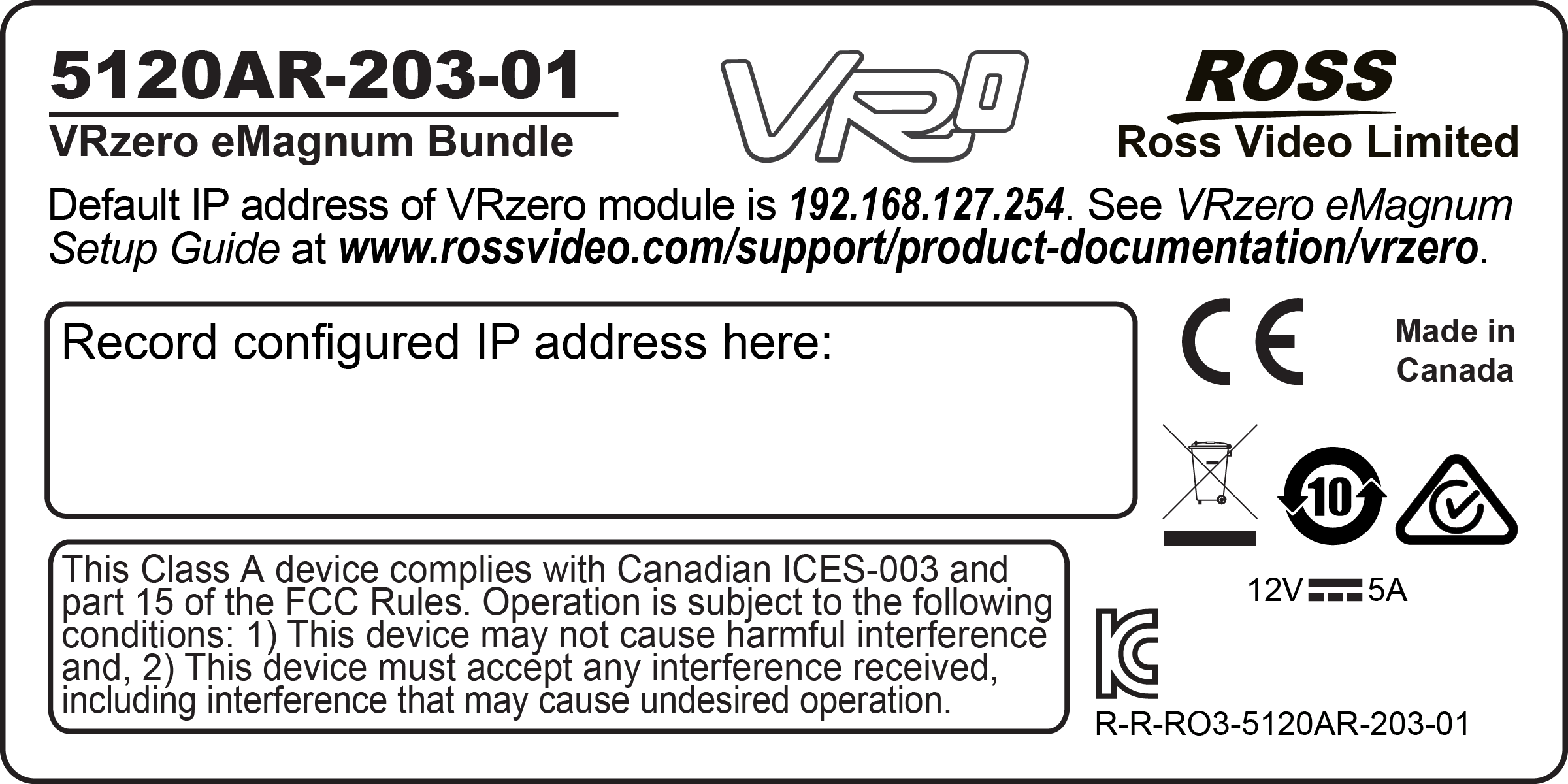
Figure 1 - - Label on the Back of the VRzero Module, with Space to Record the IP Address
-
Download and install the NPort Search Utility , which can detect the IP address. For more information, see “Finding the IP Address of a VRzero Module”.
The NPort web console application appears (see Figure ??).
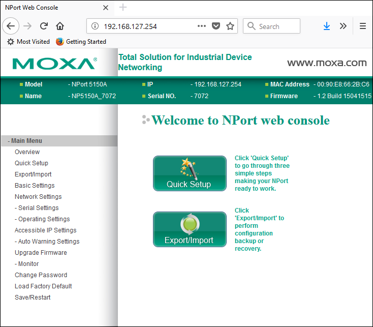
Figure 2 - - The NPort web console Application
Setting the IP Address
This section describes how to use the NPort web console to set the IP address of the VRzero module.
Notes:
- Each device on the network must have a unique IP address. The default IP address of the VRzero module is 192.168.127.254. We recommend you change the IP address to avoid problems if you later add another VRzero module later.
- IP addresses of the VRzero module and all destination systems must have identical first octets. The first octet consists of the digits before the first dot. For example, in the IP address 192.168.127.254, the first octet is 192.
- The Main Menu of the NPort web console application includes a Load Factory Default option. Do NOT use this option. It does not restore the VRzero module to Ross Video factory settings. If you need to restore the VRzero module to its original state, see “Restoring the Ross Video Default Configuration”.
To set the IP address of the VRzero module :
-
Access the NPort web console application on the VRzero module.
For more information, see “Accessing the Configuration Application”.
-
On the Main Menu , click Network Settings (shown with yellow background in Figure ??).
The Network Settings page appears.
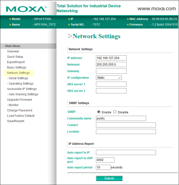
Figure 3 - - Setting the IP Address of the VRzero Module
-
In the IP address box, type the IP address you want to assign to the VRzero module.
-
Scroll to the bottom of the page, and then click Submit .
The Network Settings OK! message appears.
-
Click Save/Restart .
The VRzero module restarts. This takes approximately ten seconds.
-
Click Home to return to the Main Menu of the NPort web console .
-
On the back of the VRzero module, record the IP address you configured.
noteThe label on the back of the VRzero module has a blank area intended for recording the IP address (see Figure 4 -). Write the new IP address on the label, and obscure the old IP address (if present).
Figure 4
Figure 4 - - Label on the Back of the VRzero Module, with Space to Record the IP Address
Specifying Data Destination Addresses
The VRzero module delivers encoder data to up to four specified destinations (IP addresses).
The Main Menu of the NPort web console application includes a Load Factory Default option. Do NOT use this option. It does not restore the VRzero module to Ross Video factory settings. If you need to restore the VRzero module to its original state, see “Restoring the Ross Video Default Configuration”.
To specify data destination addresses:
-
Access the NPort web console application on the VRzero module.
For more information, see “Accessing the Configuration Application”.
-
On the Main Menu , navigate to Operating Settings > Port 1 (shown with yellow background in Figure ??)
The Operation Modes page appears.
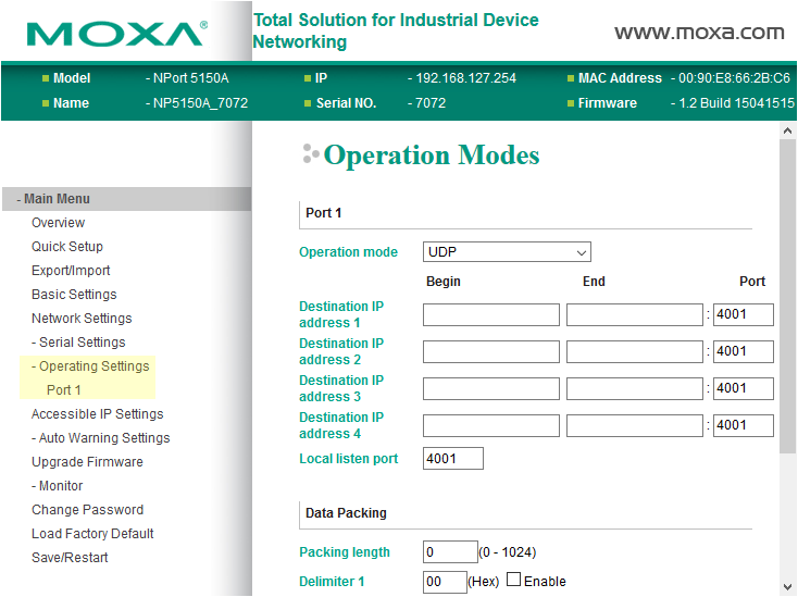
Figure 5 - - Specifying Destination IP Addresses
-
Set the Operation mode to UDP .
-
Specify one or more Destination IP address es (numbered 1 - 4, starting at number 1):
-
In the Begin column, type the IP address.
-
In the Port box, type the number of the port through which the destination system will receive the data.
tipFor Ross Video UX VCC, the default Port number is 1100 .
-
-
Scroll to the bottom of the page, and then click Submit .
The Operation Modes Settings OK! message appears.
-
Click Save/Restart .
The VRzero module restarts. This takes approximately ten seconds.
-
Click Home to return to the Main Menu of the NPort web console .
Configuring Destination Systems
The VRzero module provides real-time position-tracking encoder data that can be used by Ross Video’s Virtual Camera Controller (UX VCC) or other external systems.
This section provides information to consider when configuring your external systems to accept and use the data.
IP Address and Port
When you configured the VRzero module, you specified up to four destinations (IP address and port). The destination systems must accept communication over the ports you specified when you configured the VRzero module. You may need to specify the port number in your VCC application.
Data Channels
The data is transmitted using Kuper protocol over IP. There are 12 data channels, 4 of which carry encoder data. Configure your VCC system to receive data on the following channels:
- Channel 9 — Focus data
- Channel 10 — Zoom data
- Channel 11 — Tilt data
- Channel 12 — Pan data
Setting the Encoder Scale Value for Pan and Tilt Axes
The eSensor fluid head has 22-bit encoders on its pan and tilt axes. Your Virtual Camera Control (VCC) application must convert the raw encoder data to a format that is useful to the application.
Like many similar applications, Ross UX VCC applies a scale value to convert the raw encoder data to degrees. You must configure the application to apply the correct scale for each axis.
The required scale value is equal to 360 divided by the number of counts per revolution.
The pan and tilt encoders register 4,194,304 encoder counts per 360-degree revolution.
360 divided by 4,194,304 yields an encoder scale value of 0.0000858306884765625 .
For Ross Video UX VCC, set the pan and tilt encoder scale value to 0.00008583069 .
Reversing Axis Orientation
By default, the orientation of the pan and/or tilt axis may be reversed compared to what your VCC application expects.
For example, the VCC application may expect the pan encoder count to decrease as the eSensor fluid head pans clockwise, but the count actually increases instead.
You can effectively reverse the axis orientation by modifying the scale value in your VCC application. Multiply the scale by minus 1, by placing a negative symbol (-) before the scale value for that axis.
Calibrating the Tilt Axis by Applying an Offset Value
By default, the tilt axis encoder on the eSensor fluid head may not necessarily report a value of zero when its camera mount surface is horizontal. In VCC applications, a tilt value of zero indicates that the camera is horizontal.
To ensure that the tilt axis for your virtual camera is properly calibrated to reflect real camera tilt motion, the VCC application must be configured to compensate for the tilt encoder’s non-zero value.
You can calculate and apply a tilt offset value in the VCC application to calibrate the virtual camera tilt axis with real camera tilt motion.
A high-quality level is required for accurate calibration. We recommend using a digital level.
Ensure that the encoder scale for the tilt axis is configured in your VCC application before you try to calibrate the tilt axis. For more information, see “Setting the Encoder Scale Value for Pan and Tilt Axes”.
To calculate and apply the tilt offset value:
-
Ensure that the body of the eSensor is level.
tipThe body of the eSensor has a built-in bubble level.
-
Place a high-quality level on the camera mount surface (top) of the eSensor fluid head, and then tilt the fluid head to achieve level.
tipIf the top of the fluid head is perfectly level, panning it and/or repositioning the level should not affect the level reading. The top of the fluid head should remain level.
-
Lock the tilt axis and then check again to confirm that the top of the eSensor fluid head is still level.
-
With the fluid head level, check the VCC tilt axis value. It should read as 0 .
If the VCC tilt value is not 0 , apply an offset value to the VCC’s virtual tilt axis to compensate.