Assembly and Cabling
This section explains how to assemble and cable the components of the VRzero eMagnum Bundle.
Topics in this section include the following:
-
After you assemble and cable the components, you must configure the VRzero module. For more information, see “Configuration”.
Before You Begin
Before you begin, ensure that you have the required tools:
- 3mm hex key (also known as a hexagonal wrench, or Allen key)
- 4mm hex key
Mount the eMagnum Fluid Head, and Attach Pan Bars
These steps illustrate how to mount the eSensor fluid head to a tripod recommended and sold by Ross Video (product code RRB-EMAG-TRI ). The fluid head can mount to any Mitchell flat base heavy duty tripod.
To mount and level the eSensor fluid head :
-
Unpack the tripod and set it up.
-
Unpack the eSensor fluid head and mount it to the tripod.
-
Level the head, referring to the built-in bubble level (see Figure ??).
The head must be level to ensure that pan motion is perfectly horizontal.
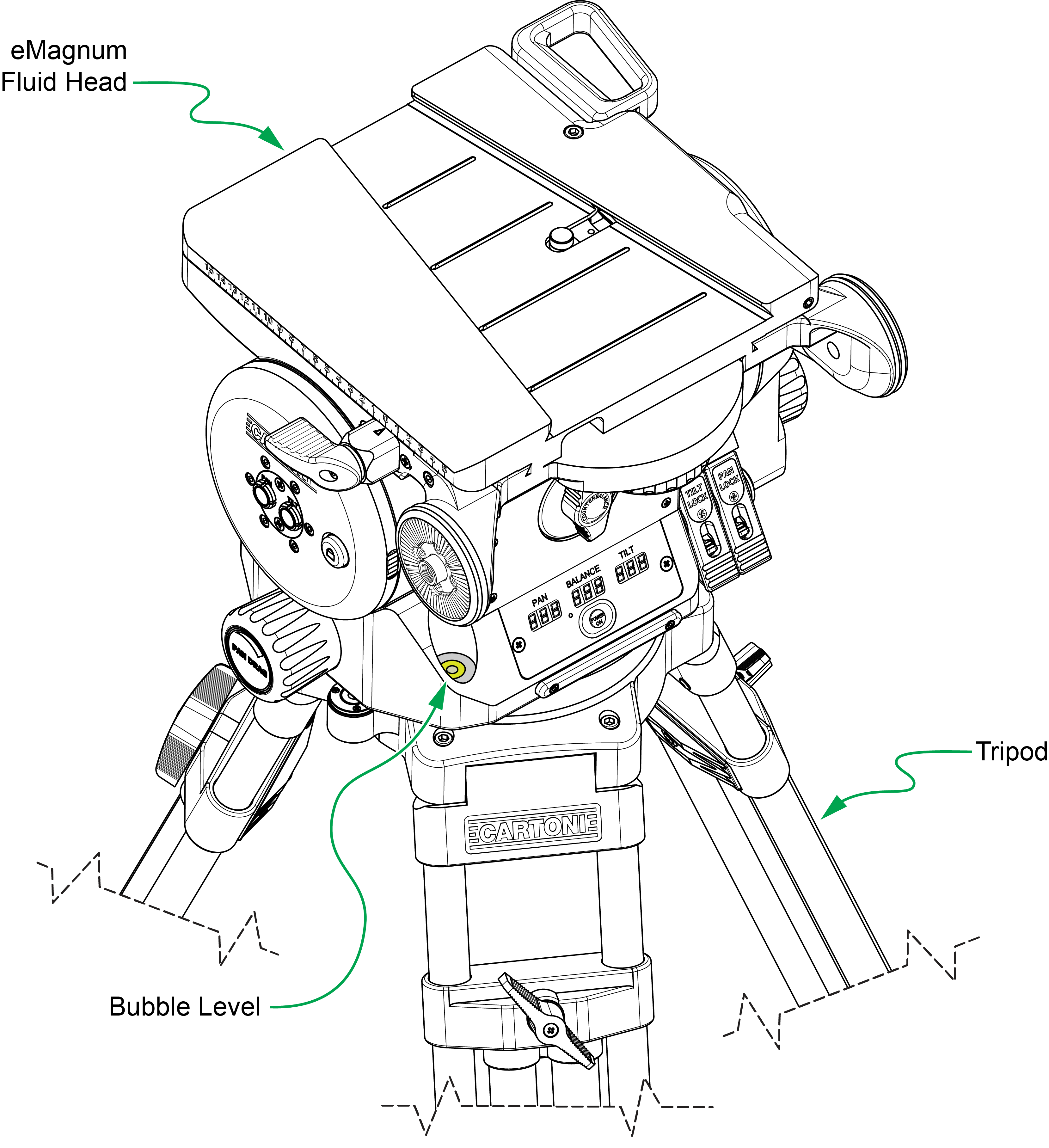
Figure 1 - - Mounting and leveling the eSensor fluid head
To attach pan bars to the eSensor fluid head :
-
Unpack the two pan bars (right and left) and determine which is which (see Figure ??).
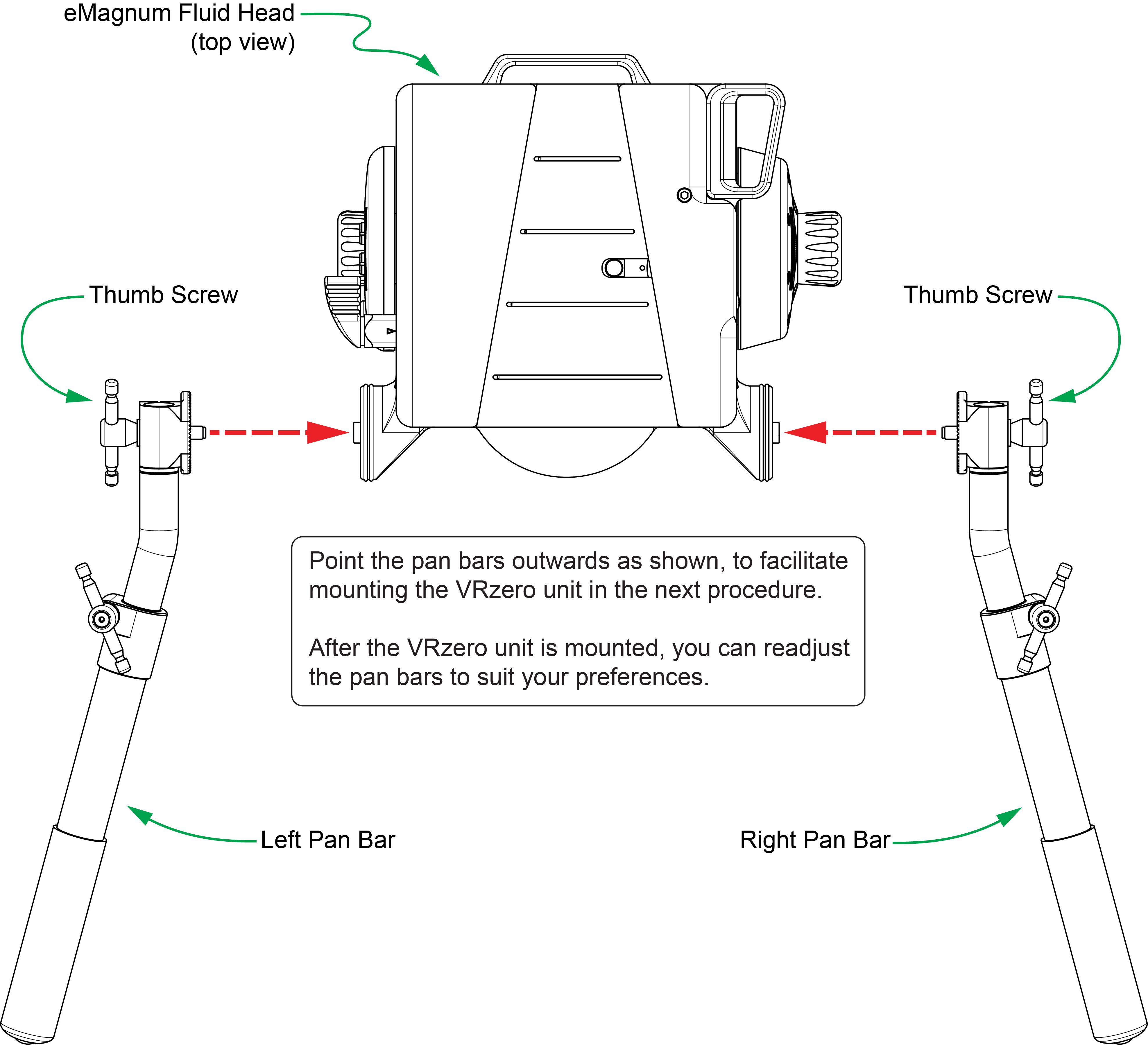
Figure 2 - - Attaching the Pan Bars to the eSensor Fluid Head (view from above)
-
For each pan bar:
-
Align the pan bar so it extends horizontally from the eSensor fluid head and points outwards (see Figure 2).
tipPointing the pan bars outwards facilitates mounting of the VRzero module in the next procedure. After the module is mounted, you can readjust the pan bars to suit your preferences.
-
Attach the pan bar to the eSensor fluid head, and secure it using the thumb screws.
tipTo fully engage the rosette connectors, wiggle the pan bar slightly as it becomes snug.
-
Mount the VRzero Module
The VRzero module mounts between the pan bars of the eSensor fluid head.
To mount the VRzero module :
-
Unpack the VRzero module and its mounting bracket (see Figure ??).
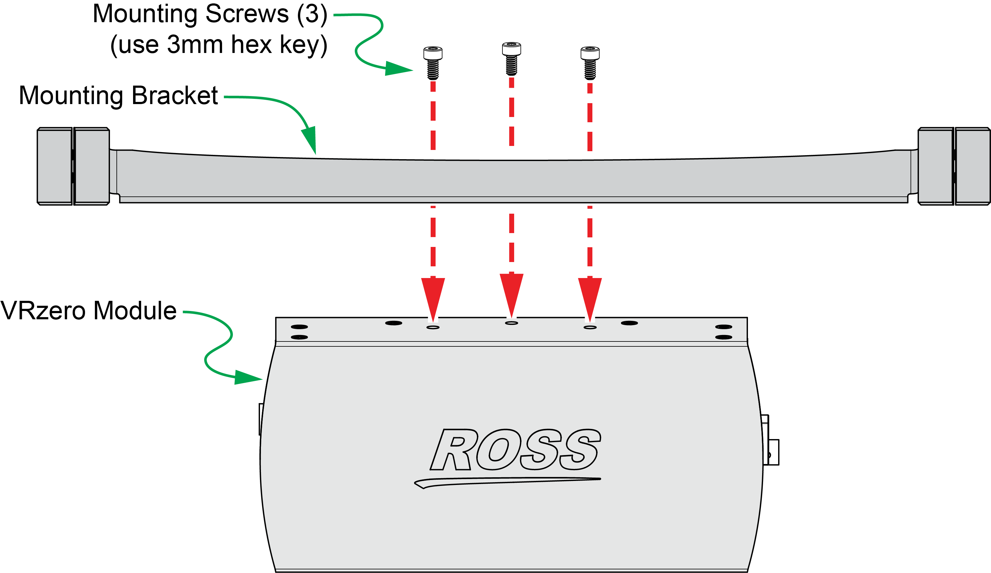
Figure 3 - - Attaching the Mounting Bracket to the VRzero Module
-
Fasten the bracket to theVRzero module (see Figure 3):
-
Mount the VRzero module on the pan bars:
- Using a 4mm hex key, remove both side clamps from the mounting bracket (see Figure ??).
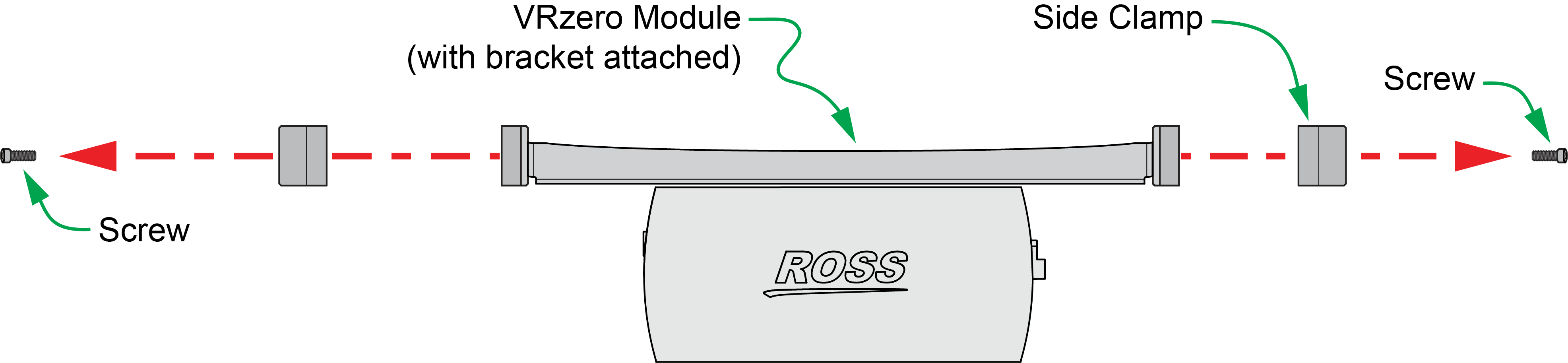
Figure 4 - - Removing Side Clamps
- Slide the VRzero module between the pan bars, positioning it no more than 1/4” (6mm) from where the pan bars meet the eSensor fluid head (see Figure ??).
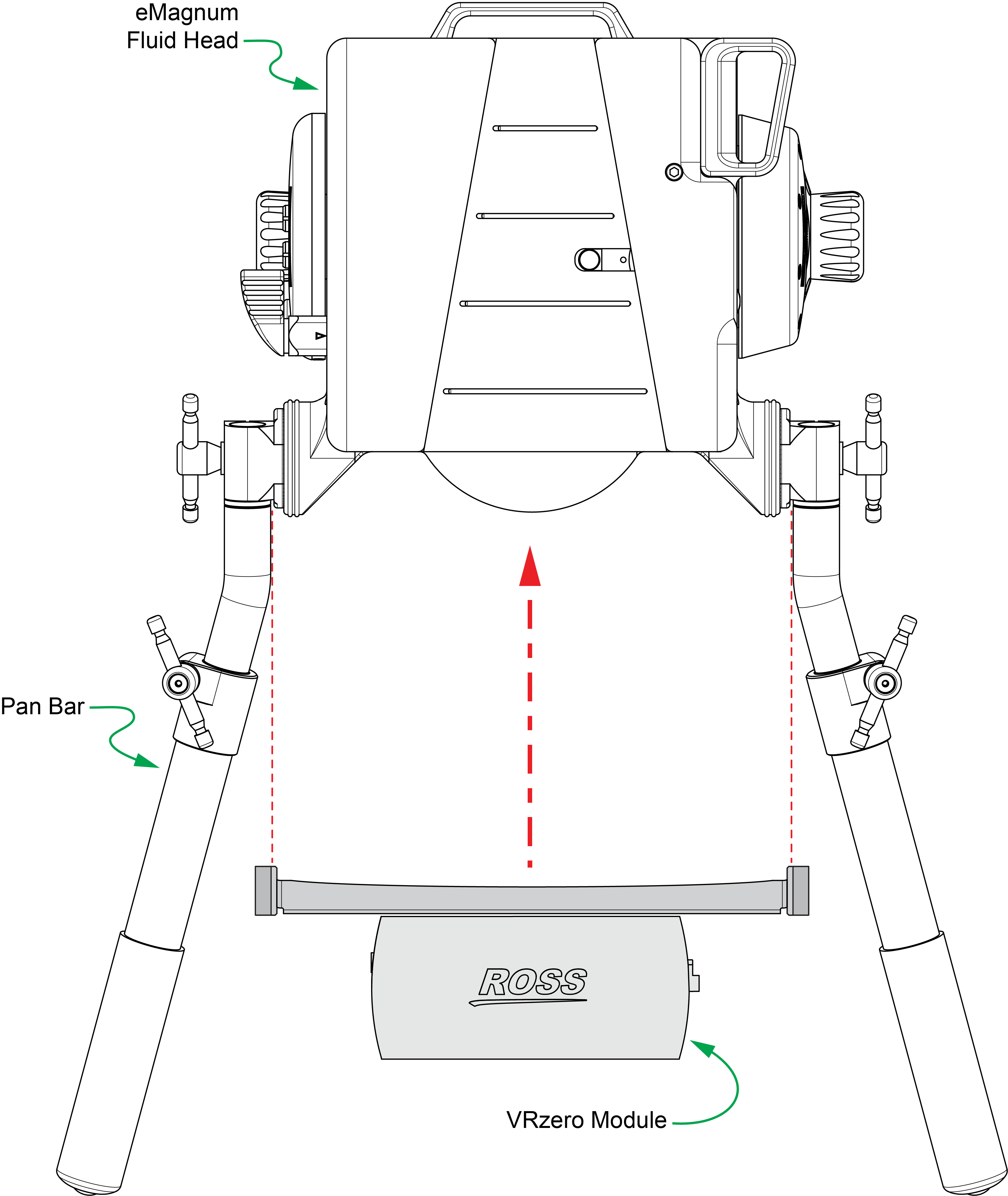
Figure 5 - - Sliding the VRzero Module onto the Pan Bars
-
Using a 4mm hex key, reattach both side clamps so they clamp the pan bars loosely.
Do not tighten the side clamp screws completely yet. Leave the side clamps slightly loose to facilitate adjustment of the pan bars.
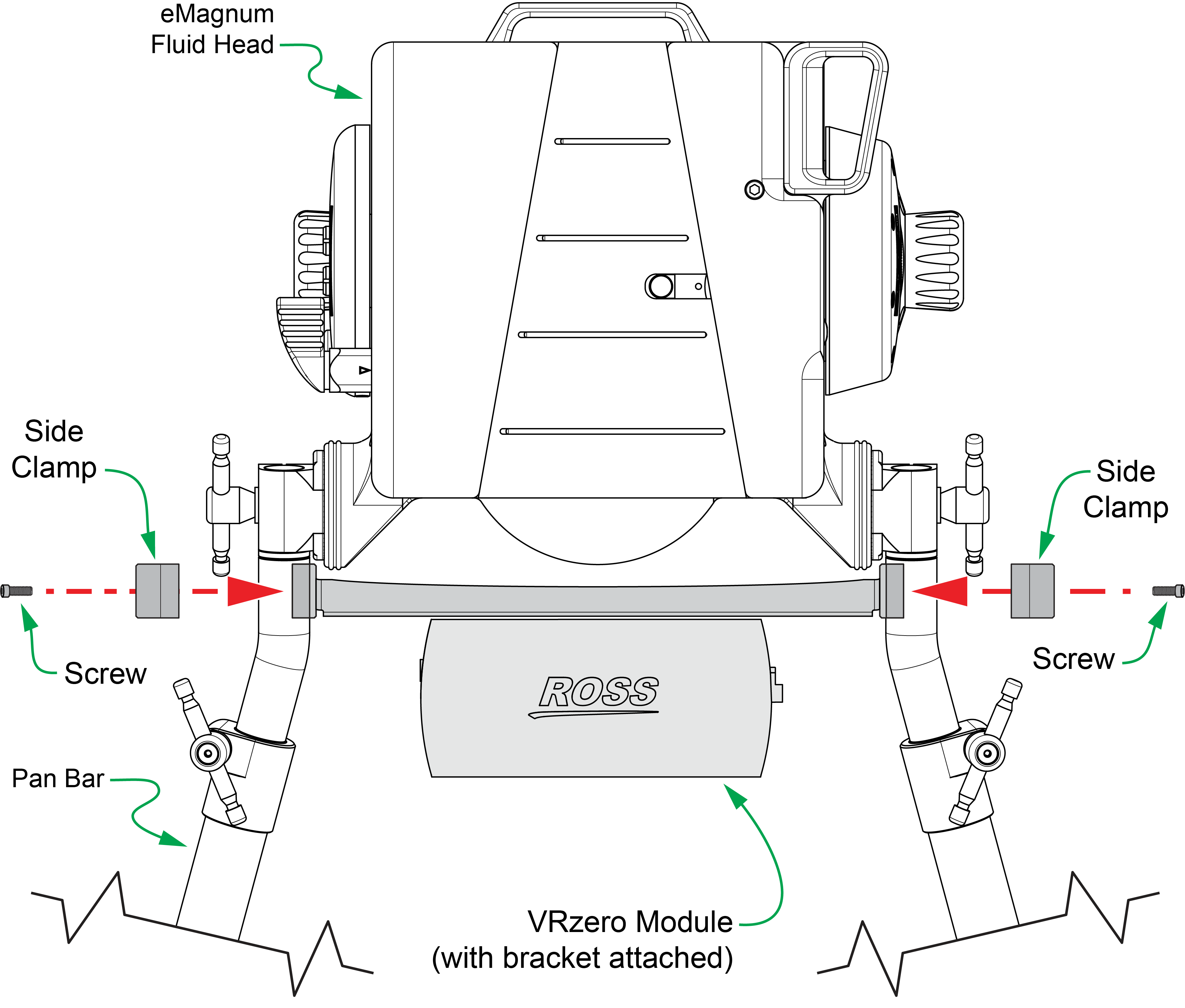
Figure 6
-
Adjust the direction that the pan bars point, to suit your preferences (see Figure ??):
- Loosen both rotation thumb screws slightly and then rotate the pan bars to adjust which way they point.
- Re-tighten both rotation thumb screws.
- Using a 4mm hex key, tighten both side clamps so they clamp the pan bars firmly. Do not over-tighten.
Figure 6 -- Reattaching the Side Clamps
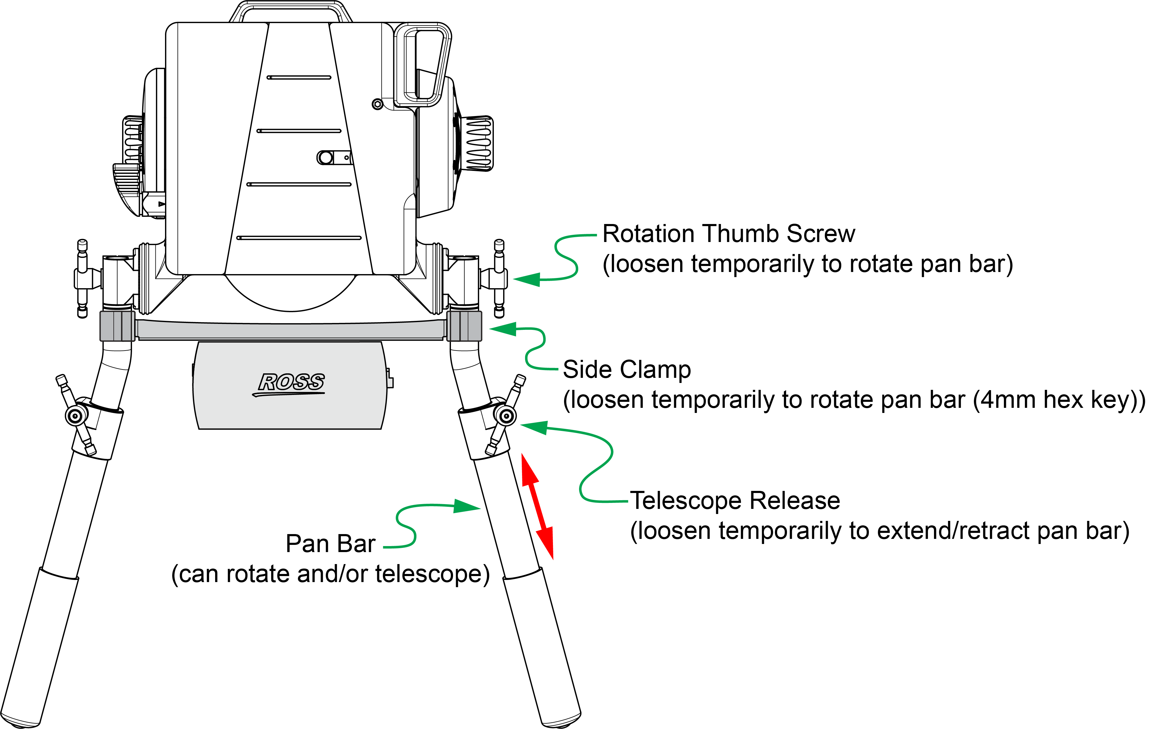
Figure 7 - - Adjusting the Pan Bars (rotate and/or extend/retract)
-
Adjust the length of each pan bar, to suit your preferences (see Figure 7):
- Loosen the telescope release.
- Slide the end section of the pan bar in/out to the desired position.
- Re-tighten the telescope release.
Cable the System
Before you cable the system, mount the camera and lens on the eSensor fluid head. You can also adjust the fluid head’s counterbalance, tilt drag, and pan drag settings as desired.
Figure ?? shows the connectors on either end of the VRzero module. The steps in this section describe how to connect cables to the module.
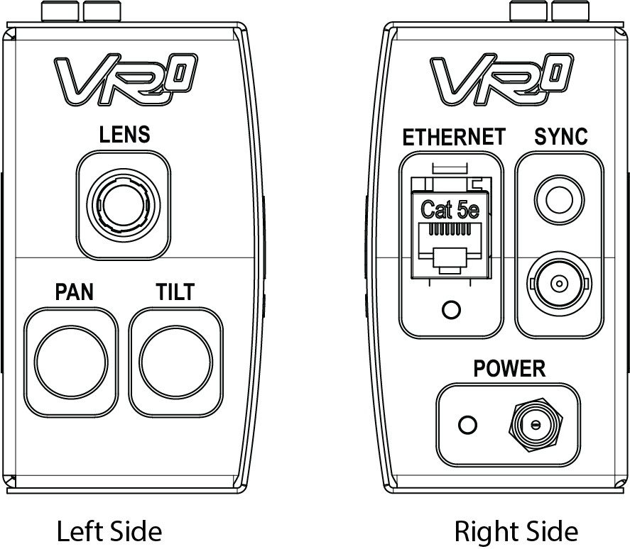
Figure 8 - - Connections on the VRzero Module
To cable the system:
-
Connect the encoder data cables (see Figure ??):
-
Connect the PAN and TILT encoder data cables from the eSensor fluid head to the VRzero module.
tipThe PAN and TILT encoder data cables are identical. They are approximately 25” (64cm) long and each has a tag showing part number 5120CR-305- xx . In Figure ??, the PAN data cable is shown as purple, and the TILT data cable is shown as green.
-
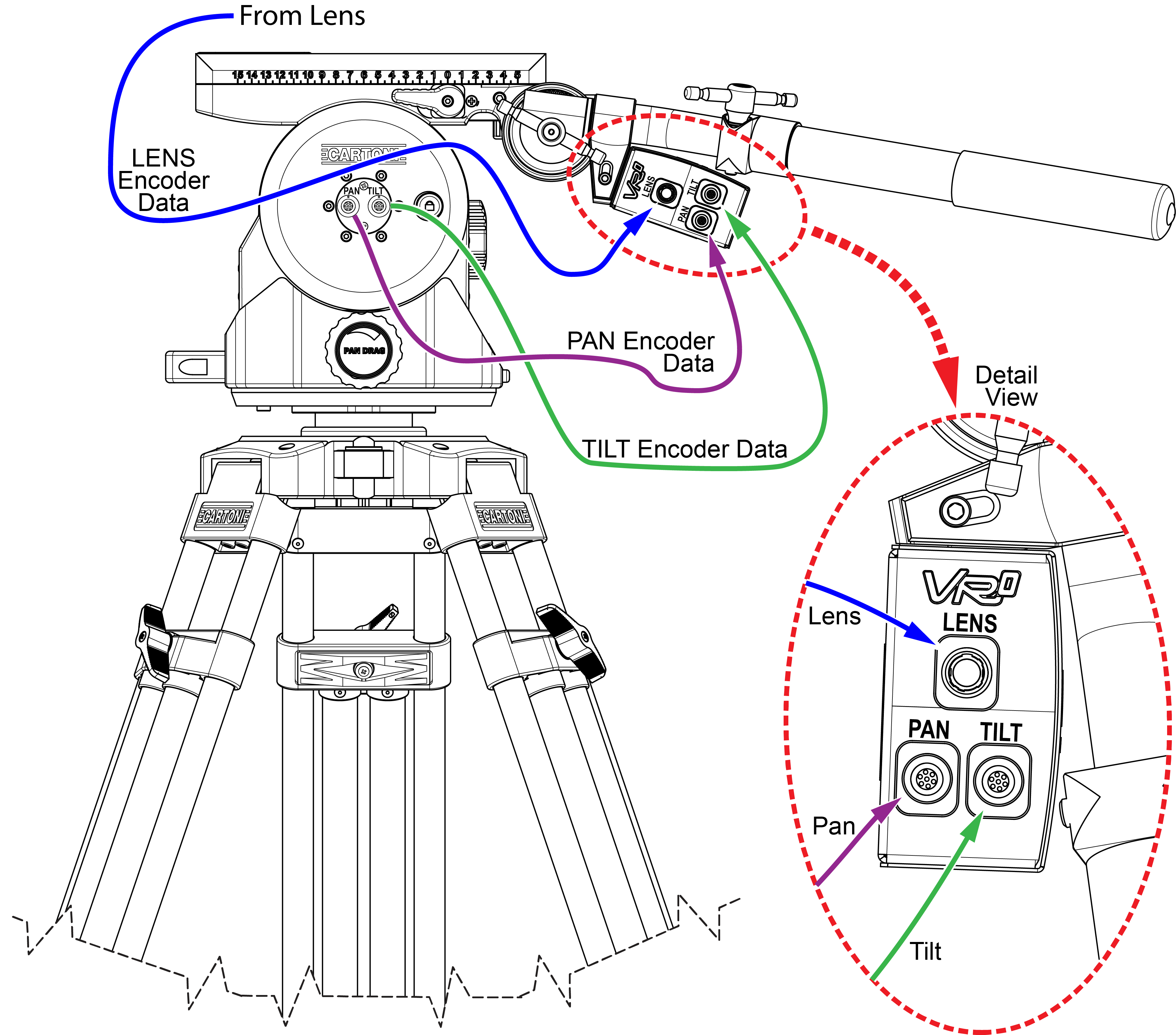
Figure 9 - - Connecting Encoder Data Cables (PAN, TILT, and LENS)
-
Connect the LENS encoder data cable from the lens to the VRzero module. In Figure 9, the LENS data cable is shown as blue.
Use the correct lens encoder cable for your lens type:
-
For Canon lenses, use Ross Video cable number 900-212- xx .
-
For Fujinon lenses, use Ross Video cable number 5100CR-029- xx .
tipBoth types of lens encoder data cable are included in the VRzero eMagnum Bundle .
-
Connect the video reference (genlock/sync) signal cable (not included) to the SYNC BNC connector on the VRzero module (see Figure 10 -).
The SYNC LED glows green when the module is connected to a video reference signal.
noteTri-level and black burst formats are supported. The VRzero module receives video reference signal only; it does not generate the signal.
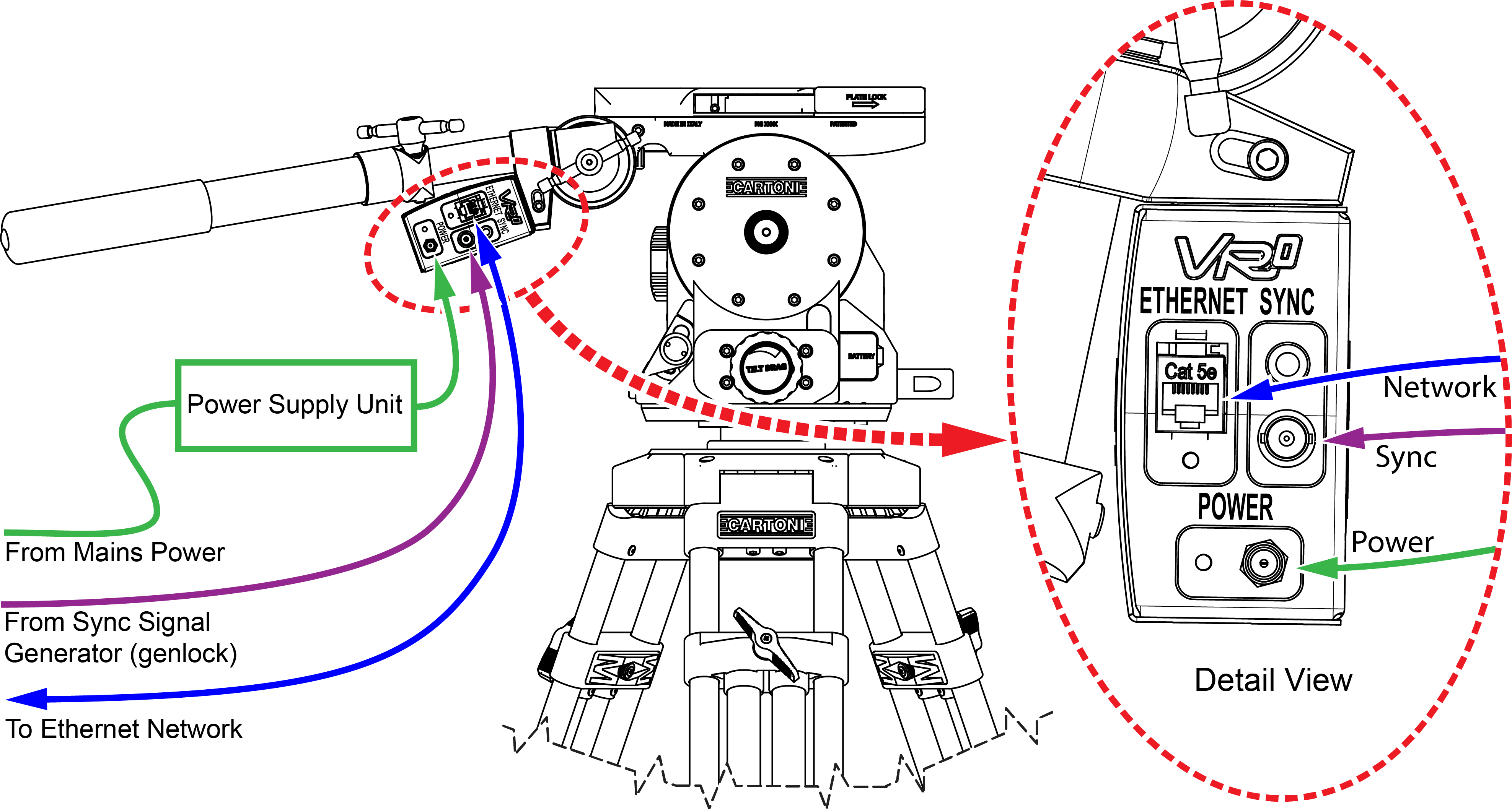
Figure 10
-
Connect an ETHERNET cable (CAT5E or better, not included) between the VRzero module and the network.
noteThe VRzero module must be on the same network as all destination systems that require the tracking data, such as a Virtual Camera Control (VCC) system.
-
Connect power cables to the camera and lens as required.
importantWhen you use the VRzero module , you must turn on the camera and lens before applying power to the module. If the camera and lens are not powered first, the VRzero module may not be able to relay lens encoder data (zoom and focus).
-
Connect the VRzero module’s power supply unit to the module’s Power input connector, and then to a standard electrical outlet.
noteThere is no power switch. When you apply power, the VRzero module turns on. The Power LED glows red while the module is initializing, and then turns green.
tipThe power plug has a threaded sleeve to secure it to the Power connector on the VRzero module . Use of this threaded sleeve is optional.
-
-
Figure 10 - - Connecting Sync, Network, and Power Cables