Installing and Configuring the System
This section describes how to install and configure a standalone Canon Camera Paint Control system for the EOS C500 Mark II camera.
Before you install the system, you need to plan the installation. For more information, see “System Overview and Planning”.
The contents of this chapter include:
- “Upgrade Canon Camera Firmware”
- “Install DashBoard Software�”
- “Set Up the Camera Control Computer(s)”
- “Set Up the Canon Camera”
- “Configure the Camera’s Network Connection”
- “Configure the Camera’s On-Screen Display”
- “Configure the Camera Picture Settings”
- “Configure Workstation”
- “Install Camera Paint Boxes”
- “Configure the Camera Paint Box Connection”
Upgrade Canon Camera Firmware
If the camera has an older version of firmware installed, you must upgrade it. Canon Camera Paint Control must connect with an EOS C500 Mark II camera running firmware version 1.0.6.1 or newer.
To install the latest Canon EOS C500 Mark II firmware:
- Go to the downloadable drivers available through Canon support.
- Download the latest driver for your camera and follow Canon’s installation instructions.
Install DashBoard Software
Install the latest version of DashBoard (v9.9 or higher) available at: https://www.rossvideo.com/support/software-downloads/dashboard
DashBoard and the DashBoard User Guide are available as free downloads from Ross Video. The DashBoard User Guide contains instructions for installing DashBoard, and is available at: https://www.rossvideo.com/support/product-documentation/dashboard
Set Up the Camera Control Computer(s)
Each workstation includes one camera control computer. This section describes how to install a camera control computer provided by Ross Video. If your computer is not provided by Ross Video, these steps may vary.
To install a Camera Control Computer and Peripherals:
-
Connect the camera control computer to the monitor, keyboard, and mouse for your workstation.
tipEnsure that the monitor is visible to the operator, and that the optical drive, accessory ports, and buttons on the right and left edges of the computer are accessible.
-
Ensure the computer is connected to your local wireless or Ethernet network.
-
Configure the networking parameters (IP address, subnet mask, and gateway).
Set Up the Canon Camera
This section describes how to perform an initial set up of the Canon camera in order to control Iris and Focus features from the DashBoard panel.
To enable automatic iris and automatic focus:
- Position and mount the camera.
- On the camera lens, find the IRIS switch and set it to the Automatic (A) position.
- On the camera lens, find the FOCUS switch and set it to the Automatic Focus (AF) position.
Configure the Camera’s Network Connection
The Canon Camera Paint Control requires wired camera connection following firmware upgrades and XC protocol to communicate with DashBoard.
To set the camera to XC protocol:
- Open the On-Screen Menu in the Canon camera.
- Selectthe Network Settings tab > Submenu Item 1 > New Conn. Setting > XC Protocol .
To establish the camera’s network connection:
-
Open the On-Screen Menu in the Canon camera.
-
Select the Network Settings tab > Submenu Item 1 > New Conn. Setting > Ethernet> Setup with Network Conn. > Automatic > Disable .
-
Enter the network credentials into the device.
noteAdd the IPv6 network information if necessary.
-
Select Create New Conn. Setting> Digest Authentication > Set Username/Password .
-
Enter the username and password.
noteKeep a record of these login credentials for future use.
-
Select Choose a Conn.Setting Save Destination > Done .
Configure the Camera’s On-Screen Display
The following section enables you to use the camera’s On-Screen Display (OSD ) modify the video output so that it’s compatible with your monitor.
In order to see on-screen display, the camera video output needs to be connected to the monitor.
To set the on-screen display monitor output:
- Open the On-Screen Menu in the Canon camera.
- Select Monitoring Setup > Submenu Item 7 > OSD Output: MON./HDMI> On .
- Connect the output of the camera to a monitor using Mon Out .
To change the video format:
If the video output is not visible, the following instructions
-
Open the On-Screen Menu in the Canon camera.
-
Select the Recording/Media Setup tab > Submenu Item 2> Resolution/Color Sampling.
-
Select the desired video format.
The Canon Camera Paint Control system can now access the On-Screen Display .
Configure the Camera Picture Settings
This section describes how to configure Canon EOS C500 Mark II picture settings optimally for your workstation. These configurations ensure the best quality performance for your video and are required for Canon Paint Control to work correctly.
To set up the lens:
For various lenses, you may see the outline of the lens on the edge of the video output.
Use the following instructions to resolve this issue.
- Open the On-Screen Menu in the Canon camera.
- Select Recording/Media Setup tab > Submenu Item 1 > Sensor Mode > Super 35mm (Cropped) .
To set up the pedestal or gain values:
If you cannot change the pedestal or gain values on the camera using the panel, you must Unprotect the Custom Picture (CP) file that is in use on the camera. When CP is protected, changes to the color or black gains are restricted.
-
Open the On-Screen Menu in the Canon camera.
-
Select the CP (Custom Picture ) tab > Select CP File .
noteIf the file has a Key symbol next to it, it is protected, and changes cannot be made to color settings.
-
Choose the desired CP File from the drop-down menu provided.
-
Select Edit CP File then change Protect setting to Unprotect .
You can now make changes to Pedestal and Gain values on the camera.
To enable smooth gain adjustment:
-
Open the On-Screen Menu .
-
Select the Camera Setup tab > Submenu Item 2 .
-
Set Gain Increment to Fine .
To use Kelvin scale values for White Balance color temperature:
-
Open the On-Screen Menu .
-
Select the Camera Setup tab > Submenu Item 3 .
-
Set C. Temp. Increment to Kelvin .
Canon Camera Paint Control only supports Kelvin scale values for White Balance color temperature.
Configure Workstation
This section describes how to configure DashBoard for a single computer that connects directly to cameras.
If you want to have additional workstations, set up a DashBoard proxy server. Follow the steps in this section for the proxy server computer only, and then configure the other workstations to access the cameras through the DashBoard proxy server. For more information about how to configure a DashBoard proxy server, see the DashBoard User Guide (8351DR-004-xx).
To perform the steps in this section, you need to have good working knowledge of basic computer networking procedures.
To add a camera:
-
Open DashBoard.
-
Select the + button from the Basic Tree View .

Figure 1
-
Tip : You can alternatively select File > New > Other .
-
Expand Cameras , select Canon Cinema Camera , and then select Next .
The Canon Cinema Camera dialog box appears.
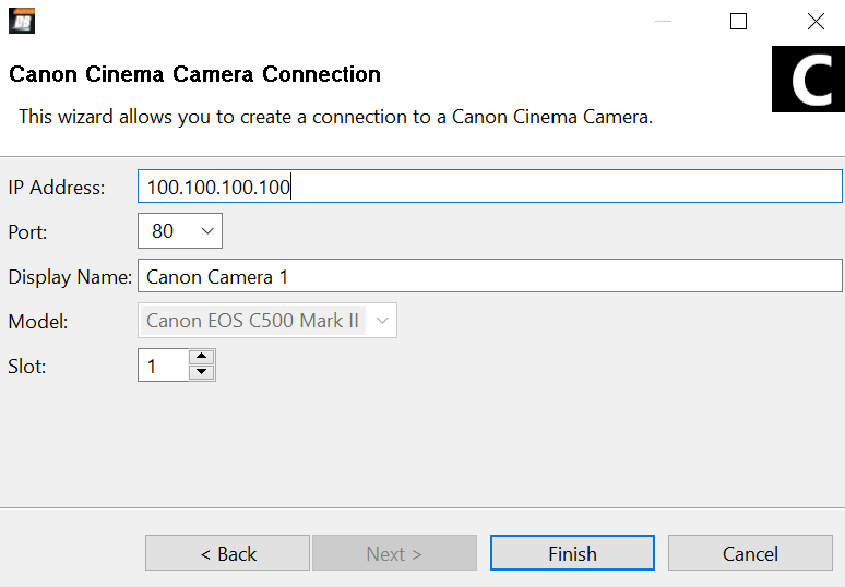
Figure 2
-
In the IP Address field, enter the IP address of the camera you want to add.
-
Enter the Port number for the camera you want to add.
-
Enter a desired Display Name , ensuring it’s unique from other display names already in use.
-
In the Slot box, specify a slot number for the camera. Valid slot numbers start at 1 .
noteAssigning a slot number is optional. If left blank, DashBoard assigns the lowest available slot number by default.
-
If the camera fails to appear in the DashBoard tree, or appears with a red dot, do the following:
- Ensure that power is connected to the camera, and that the cameras is turned ON .
- Check the IP address you typed in Step 4 and ensure that it matches the IP address of the camera.
To view camera controls:
- In the DashBoard Component Tree , expand the Canon Cameras node.
- Expand the Slot node for the camera you just added.
- Double-tap Remote Control .
To enter a license key:
-
When you add the first camera to DashBoard, you will need to apply a license.
The remote control page will show a warning message:
Figure 3
-
DashBoard supports two licensing options: Software-Based Licensing and Ross Key Based Licensing .
Software-Based Licensing involves connection of DashBoard to the Ross activation server either directly or via a Ross Product Manager licensing server on prem. To use software-based licensing, you will need a product key provided by Ross.
Ross Key Based Licensing is a fixed license tied to your hardware. During the licensing process you will need to send a key code to Ross technical support who will return a license key for you to enter into DashBoard.
For more information, refer to the DashBoard User Guide 8351DR-004-XX .
To apply a software-based License
- From the main toolbar, select Window > Preferences . Refer to Figure ??.
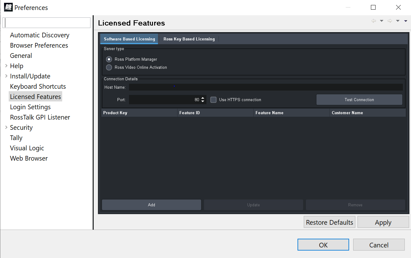
Figure 4 - DashBoard Licensed Features - Software Based Licensing tab
-
The Preferences dialog box opens.
-
From the Preferences dialog box, select Licensed Features .
-
In the Licensed Features dialog box, ensure the Software Based License tab is selected.
-
Select the Server type that you are using to provide licensing.
-
If you are using the Ross Platform Manager server type, enter the Host Name and Port of the server and whether to Use HTTPS connection .
Note: Select Apply to save your server settings.
Note: Use the Test Connection button to confirm a successful connection if necessary. -
Once connection to the server is established, select Add and enter the product key provided to you.
If successful, the feature you added will appear in the Licensed Features table.
Note: Select Apply to confirm your changes.To apply a Ross key based license
For obtaining and entering a Ross licensing key code, complete the following: -
From the main toolbar, select Window > Preferences . Refer to Figure ??.
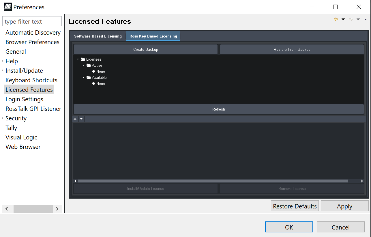
Figure 5 - DashBoard Licensed Features - Ross Key Based Licensing tab
-
The Preferences dialog box opens.
-
From the Preferences dialog box, select Licensed Features .
-
In the Licensed Features dialog box, ensure the Ross Key Based License tab is selected.
-
From either the Active or Available subfolder, select the Canon Camera Control feature.
-
To obtain a Ross License Key by completing the following:
Click Install/Update License .
ii. The Enter License Key dialog box opens. Refer to Figure ??.
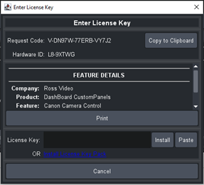
Figure 6 - DashBoard Licensed Features - Enter License Key
-
iii. Select Copy to Clipboard to copy your request code.
iv. Paste the request code into an e-mail to Ross Video (techsupport@rossvideo.com), requesting a corresponding license key. Be sure to include the original Ross Video sales order number.
cautionDo not close the Enter License Key dialog box until you receive and apply an activation code from Ross Video. If you leave the Enter License Key dialog box, the activation code you receive will not work. It is valid only for the session during which it was generated.
When you receive the license key via email, copy and paste it into the License Key box, and then tap Install.
vi. The selected feature updates and the most current data is displayed in the License Details .
- Close and reopen the Canon Cinema Camera tab to refresh the page after you have applied the license.
To link/unlink camera selection between Canon Camera Paint Control and other control interfaces:
-
Open the DashBoard Component Tree , navigate to DashBoard Services , and then double-tap Selector UI Mappings .
The Selection Mapping interface appears.
You can use the UI Follows Selection buttons (OFF / ON ) to control whether selecting a camera in one interface selects it in all interfaces.

Figure 7
-
Do one of the following:
-
To turn Selection Follow ON , select the ON button.
If you select a camera in one interface, it becomes selected in all others. For example, if you select a camera on a joystick panel, it is also selected in SmartShell and in the Camera Control Panel.
noteSmartShell must be configured for Selection Follow . For more information, contact Ross Video Technical Support.
-
To turn Selection Follow OFF , select the OFF button.
Camera selection in the Camera Control Panel is independent of camera selection in other interfaces.
-
Install Camera Paint Box es
The Camera Paint Box is an optional accessory that enables physical control of paint settings. Each work station may or may not include a Camera Paint Box.
![]()
Figure 8
To install a Camera Paint Box :
-
Position the Camera Paint Box in the camera control workstation location.
Ensure that the Camera Paint Box is within easy reach of the operator.
The Camera Paint Box can sit on a flat surface, or occupy 1RU in a standard 19” component rack.
-
Plug one end of the provided USB cable into the Camera Paint Box. Plug the other end into a USB connector on the back of the camera control computer.
-
Plug the power cable into the Camera Paint Box, and into a suitable power outlet.
On the front of the Camera Paint Box, a green LED indicates that the unit is powered.
Configure the Camera Paint Box Connection
Each camera paint box is connected to a camera control computer via a USB cable.
DashBoard communicates with the Camera Paint Box through a service called the bridge server. To establish communication with the Camera Paint Box, you must:
- Install the bridge server software.
- Add and configure a DashBoard gateway for the Camera Paint Box.
The Green Pedestal and Green Gain have no effect on the Canon camera.
Steph is looking at creating a simple installer for this.
To install the bridge server software:
-
Obtain the Bridge Server software zip file from Ross Video, and save it on the camera control computer.
-
Unzip the file to C:\Ross.
-
Open a command prompt window as Administrator , and change directory to the location where you unzipped the file, for example:
cd "C:\Ross\Bridge Server 6.0.300.8105"
-
Enter the command to install the ManagedServicesHost.exe file and then press Enter . An example of the command is as follows:
C:> "Ross\Bridge Server 6.0.300.8105\ManagedServicesHost.exe" -install
-
Press Enter .
The Bridge Server software is installed. A message in the command prompt window appears when the installation is complete.
-
Close the command prompt window.
-
In a web browser, navigate to the Bridge Server configuration page at localhost:3000 .
-
If the PaintBox Bridge service is not running, select Start .
tipFrom the configuration page, you can start or stop the server. Alternatively, you can start or stop the Bridge Service Host from the Services tab in Windows Task Manager .
To add a DashBoard gateway for the Camera Paint Box :
-
In DashBoard, from the File menu, select New , and then select TCP/IP DashBoard Connect or openGear Device .
The New TCP openGear Frame Connection dialog box appears.
-
In the IP Address box, enter the IP address of the computer, or enter localhost.
-
In the Display Name box, enter a name for the node as you want it to appear in the DashBoard component tree, for example, Robotics DashBoard Gateway .
-
Select the JSON protocol.
-
In the Port box, enter the desired port number.
-
Select the Remember connection settings for this frame check box.
-
Select Finish .
A new gateway node with the name you specified appears in the DashBoard component tree.
tipAfter you complete this procedure, you can expand the gateway node and double-clickselect Station 1 to open an interface that displays real-time data received from the Camera Paint Box .
To configure a DashBoard gateway for the Camera Paint Box :
- In the DashBoard component tree, expand the DashBoard Services node.
- Select Device Class Mappings .
- For each Class , in the Selected Device list, select the only available option in the list.
- In the DashBoard component tree, select Selector UI Mappings .
- Set the Autowire Follows UI setting to ON .