
To Create a Router Database
The router uses the database to identify sources and destinations and assign them to levels.
Important: The switcher can only access the first 4000 destination and source database entries on the router.
Destinations or sources with an ID beyond 4000 are not addressable by the switcher. When you are building your database, on the sources table you should
populate the SDI inputs from each blade first, followed by the virtual inputs that are mapped to switcher aux buses, and finally audio channels. For the destinations table, you should
populate the switcher outputs from each ME first, followed by the virtual outputs that are mapped to switcher aux buses, and finally audio channels, UltriScape
heads, and PiP outputs.
Note: Ensure that you have the UltriMix option installed. This is needed to properly route audio. Refer to the documentation that came with your router
for information on installing options.
- From the DashBoard tree view for the router, expand the Ultrix > Database node.
-
Double-click Database Builder.

-
Select the configuration for the database as follows:
Option Description Enter a name for the new database Enter a unique identifier for the database. This name is used to identify sources and destination on this router on the network. Select one or more frames to be included for the database creation Select the router you are currently setting up. Do you want to include AUX ports? On the router, AUX ports are the SFP ports located on the SDI IO boards. Refer to the Ultrix™ manual for information on setting up and using the SFP ports. Do you want to support video signal? Select Yes. How many audio channels do you want to add? Select the number of audio channel you want to support. The default is 16. Do you want to add breakaway source support? Select Yes and enter the number of SDI and MADI audio channels you want to support. Do you want to add disconnect source? Select Yes. The disconnect source is used to mute audio channels as well as provide black for switcher aux buses. Do you want to add passthrough source? Select Yes. This allows audio sources to follow video and bypass the audio processing. Do you want to add virtual ports? Select Yes. Virtual ports are used for Aux buses, as well as audio meters and mixers. Do you want to add Ultriscape support? UltriScape provides the MultiViewer outputs for the switcher and router. Number of Multiviewer heads Select the number of Multi-Viewer outputs you want. Number of Multiviewer pips per head Select the number of boxes/pips you want per Multi-Viewer output. Include detected Multiviewer layout If you have any Multi-Viewer layouts already on the system, you can include them. Select the number of Multi-Viewer heads (outputs) and boxes (pips) you want in each. - Click Next.
-
The mixer allows audio to be routed to and from the switcher.

Note: Refer to the documentation that came with your router for information on setting up the Mixer I/O. The switcher needs the audio sources and destinations to route audio, but your overall needs for the mixer may be different.Option Description Do you want to include the Audio Mixer I/O Map? Select Yes. Do you want to include Audio Mixer Direct Outputs? Select whether to allow the use of audio mixer resources without tying up a mixer output. Select one or more frames to be included for the mixer database creation Select the router you are currently setting up. Start Audio Levels for Destinations: The destination that you want to start assigning audio. Channels per Destination: The number of levels to assign for every destination. Destination Name (prefix): The prefix for the name of the audio destination. Starting Number for Destination (postfix): The suffix number to the audio destination. Starting Audio Level for Sources: The source that you want to start assigning audio. Channels per Source: The number of levels to assign for every source. Source Name (prefix): The prefix to the name of the audio source. Starting Number for Source (postfix) The suffix number to the audio destination. - Click Next.
-
Set the name and color used for each level in the matrix.
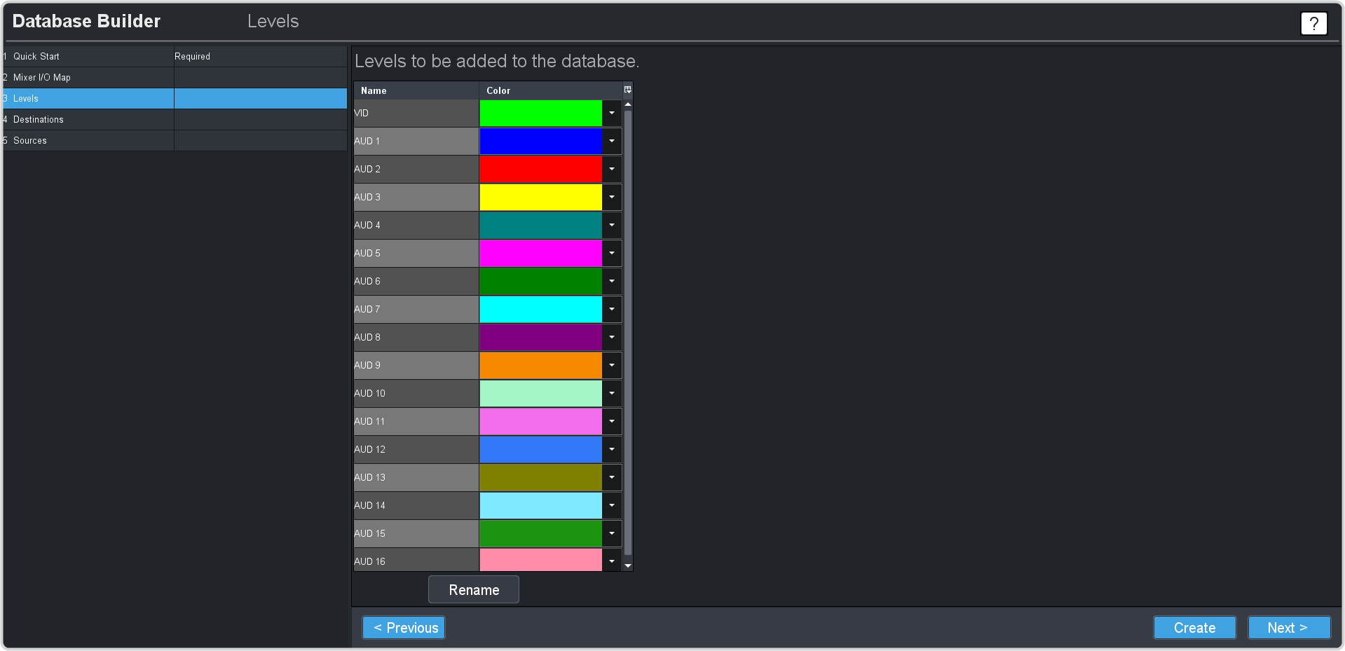
- Click Next.
-
The destinations are the outputs from the crosspoint matrix that can be assigned to outs as well as are the inputs to the switcher. You can change the Name for
any destination on the list. The destination names are use on the Soft Panel to assign sources to destinations.
Note: The switcher menus handle the assigning of router sources to switcher inputs.Tip: The format of the VID designation is frame.slot.out[number].sdi.ch1. For example, DST7 is mapped to Ultrix-5ru.flex.out[7].sdi.ch1 which is the SDI signal on HD-BNC output 7 of the blade in the FLEX slot. Your destinations will vary depending on the configuration of your system.

- Click Next.
-
The sources are the inputs to the crosspoint matrix from the input BNCs as well as outputs from the switcher. You should change the Name of the sources from the
switcher to the actual video output signal that is coming from the switcher.

Tip: An ME can be assigned to an SDPE blade installed in any slot. Refer to SDPE Slot for information on what slot and ME each SDPE blade is setup as.Note: Prior to v11.2 ME 1 was located in slot 1. With v11.2 all new systems have ME 1 located in slot 8 by default.Table 1. Default ME 1 Switcher Video Output Mapping VID Switcher Output Ultrix-5ru.slot8.in[1].sdi.ch1 ME1 PGM A Ultrix-5ru.slot8.in[2].sdi.ch1 ME1 PVW A Ultrix-5ru.slot8.in[3].sdi.ch1 ME1 PGM B Ultrix-5ru.slot8.in[4].sdi.ch1 ME1 PGM C Ultrix-5ru.slot8.in[5].sdi.ch1 ME1 User Out 1 Ultrix-5ru.slot8.in[6].sdi.ch1 ME1 User Out 2 Ultrix-5ru.slot8.in[7].sdi.ch1 ME1 User Out 3 Ultrix-5ru.slot8.in[8].sdi.ch1 ME1 User Out 4 Ultrix-5ru.slot8.in[9].sdi.ch1 ME1 PVW B Ultrix-5ru.slot8.in[10].sdi.ch1 ME1 PGM D Ultrix-5ru.slot8.in[11].sdi.ch1 ME1 Media-Store CH1 Ultrix-5ru.slot8.in[12].sdi.ch1 ME1 Media-Store CH1 Alpha Ultrix-5ru.slot8.in[13].sdi.ch1 ME1 Media-Store CH2 Ultrix-5ru.slot8.in[14].sdi.ch1 ME1 Media-Store CH2 Alpha Ultrix-5ru.slot8.in[15].sdi.ch1 ME1 Media-Store CH3 Ultrix-5ru.slot8.in[16].sdi.ch1 ME1 Media-Store CH3 Alpha Table 2. Default ME 1 Switcher Audio Output Mapping AUD Switcher Output Ultrix-5ru.slot8.AUXA-in[1].audio.ch1 ME 1 Media-Store Audio Channel 1 (left) Ultrix-5ru.slot8.AUXA-in[1].audio.ch2 ME 1 Media-Store Audio Channel 1 (right) Ultrix-5ru.slot8.AUXA-in[1].audio.ch3 ME 1 Media-Store Audio Channel 2 (left) Ultrix-5ru.slot8.AUXA-in[1].audio.ch4 ME 1 Media-Store Audio Channel 2 (right) - Click Create to create the new database and apply it to the router.
-
Double-click the System Status and click on the Database tab.

- In the Database Management section, click on the Load Database Name list and select the database you just created.
-
Click Load.
Your new database has been created and is being loaded onto the router.