Customizing the Monogram Creator
Monogram Creative Console is a highly customizable control panel consisting of physical control modules that can be pulled apart and rearranged anytime to create a control surface that truly suits your ergonomic needs and personal preferences.
Additionally, you can use the Monogram Creator application and Ross Video DashBoard to configure many aspects of your Monogram Creator, including how each control looks (halo colors, text on Core module screen), and what each control does (assigned functions, responsiveness).
This section describes how to customize your Monogram Creative Console. It includes the following topics:
- “About Monogram Creator and DashBoard”
- “Physically Rearranging Modules”
- “Loading and Saving Configuration Profiles and Joystick Files”
- “Editing Controls in Monogram Creator”
- “Linking Physical Controls to DashBoard Parameters”
- “Updating Software”
About Monogram Creator and DashBoard
The Monogram Creator works in conjunction with the Monogram Creator application and Ross Video DashBoard to define the appearance and function of Monogram Creator controls.
Monogram Creator enables you to modify appearance settings, such as halo colors around all controls, and text on the Core module screen). You can also adjust the velocity sensitivity for some controls, such as Orbiter pad controls (commonly used for pan/tilt).
Monogram Creator and DashBoard work together to map physical controls to DashBoard controls:
-
In Monogram Creator, configuration profile settings assign joystick axis numbers to physical axis controls such as orbiter rings and dials, and assign button numbers to physical buttons.
You can assign up to 24 buttons (0 - 23 ).
You can assign up to seven axes (0 - 6 ). Although Monogram Creator allows you to assign up to eight axes, DashBoard recognizes only seven (0 - 6 ). If you assign a value of 7 , that axis is ignored in DashBoard.
-
In DashBoard, joystick settings map these numbers to DashBoard parameters, thus enabling you to change DashBoard parameter values in DashBoard plugins and CustomPanels by manipulating physical Monogram controls.
Monogram configuration profiles and corresponding DashBoard joystick settings files can be saved for later use. This enables operators to develop their own customized control panel layouts. For more information see “Save a Configuration Profile and Corresponding a Joystick File”.
Physically Rearranging Modules
You can physically rearrange Monogram Creator modules anytime to create a control surface that truly suits your ergonomic needs and personal preferences.
Modules attach to each other magnetically. Each module has one set of connection pins and multiple sets of connection pads (Figure ??). Each set of connection pins align with a set of connection pads.
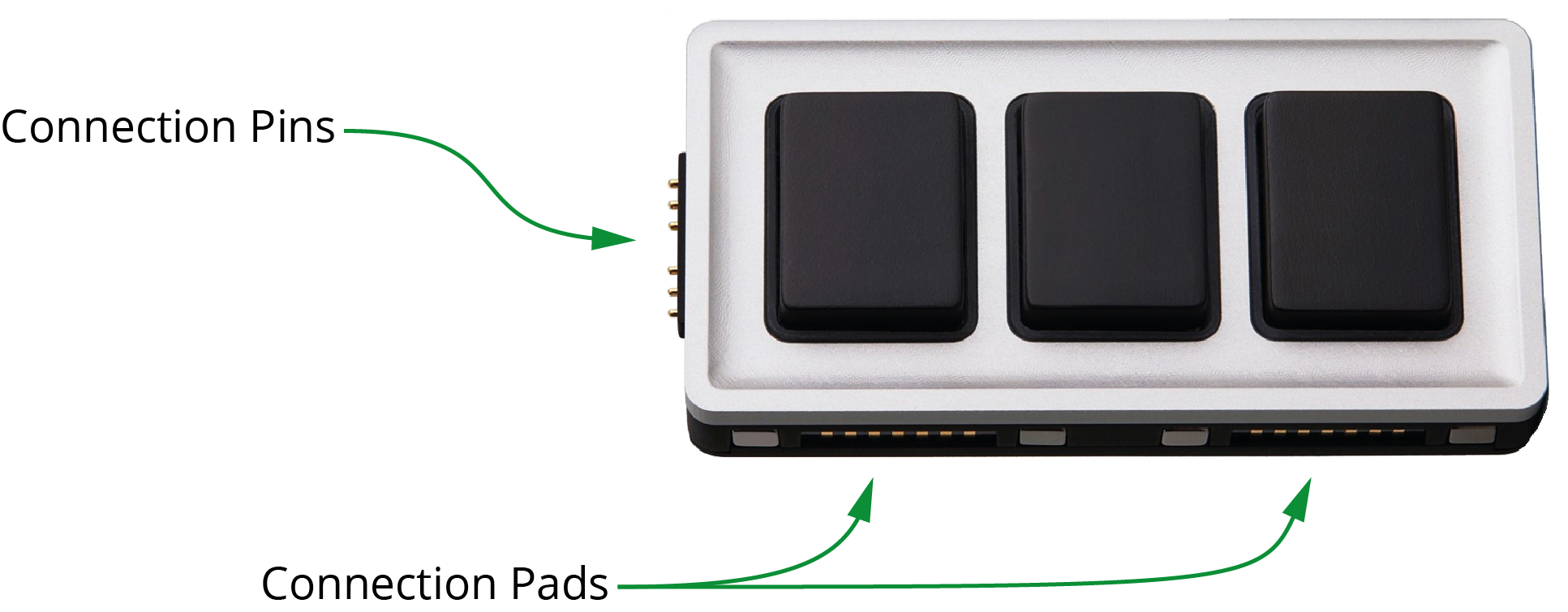
Figure 1 - An Essential Keys Module, showing Connection Pins and Connection Pads
To rearrange modules:
-
Pull the modules apart, being careful not to unplug the USB cable from the Core module.
tipIf you accidentally unplug the Core module, plug it back in, close DashBoard, and then reopen DashBoard. DashBoard detects the Core module only if the module is already plugged in when DashBoard starts.
-
Rearrange and gently reattach the modules, ensuring that each module’s connection pins are aligned with a set of connection pads on either the Core module or on an already-connected module.
tipAs you connect each module, colored rings (halos) light up around each control. If halos do not appear when you connect a module, check that its connection pins are aligned with connection pads on a module that has lit halos.
Loading and Saving Configuration Profiles and Joystick Files
Monogram Creator works in conjunction with DashBoard to map the Monogram Creator’s physical controls to functions available in DashBoard plugins and DashBoard CustomPanels.
Monogram configuration profile settings assign joystick axis numbers to physical axis controls such as orbiter rings and dials, and assign button numbers to physical buttons. DashBoard joystick settings map these numbers to DashBoard parameters, thus enabling you to change DashBoard parameter values in DashBoard plugins and CustomPanels by manipulating physical Monogram controls.
Monogram configuration profiles and corresponding DashBoard joystick settings files can be saved for later use. This enables operators to develop their own customized control panel layouts.
Load a Configuration Profile and Correspondin g Joystick File
When you load a configuration profile in Monogram Creator, typically you must also load a corresponding joystick file in DashBoard.
For steps to load a Monogram configuration profile, see “Download and Load a Configuration Profile”.
For steps to load a DashBoard joystick file, see “Load a Joystick File”.
Save a Configuration Profile and Corresponding a Joystick File
When you edit a configuration profile in Monogram Creator or modify DashBoard joystick settings, the changes persist locally even if you close the applications and restart them, or if you restart the computer. The changes are not automatically saved to the original configuration profile file or DashBoard joystick file.
This section describes how to save Monogram configuration profiles and DashBoard joystick files so you can later load the saved settings.
When you save a configuration profile in Monogram Creator, typically you must also save a corresponding joystick file in DashBoard. We recommend that you save and name configuration profiles and corresponding joystick files in pairs so it’s easy to know which ones go together.
To save a Monogram configuration profile:
-
In Monogram Creator, on the File menu, select Save Profile .
The Save Monogram Profile dialog box appears (Figure ??), and shows the folder where a configuration profile was most recently saved or loaded.
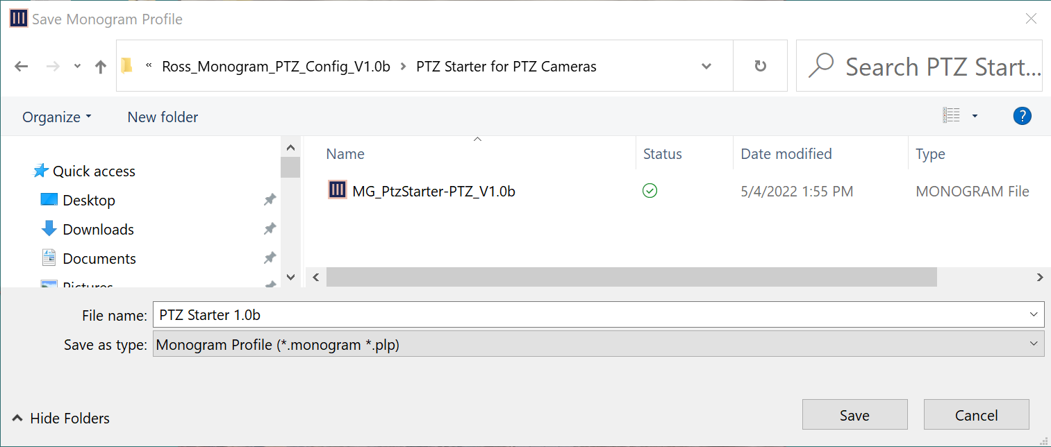
Figure 2 - Save Monogram Profile Dialog Box
-
Navigate to the folder where you want to save the profile.
-
In the File name box, specify a name for the profile.
tipBy default, the File name box is populated with the profile icon text that appears on the Core module’s LCD display.
-
Select Save .
The profile is saved.
To save a DashBoard joystick file:
-
In the DashBoard tree, expand the Game Controllers node and then double-click the Monogram Creator’s node.
DashBoard configuration settings for the Monogram Creator appear, including lists of Device Classes , Axis Controls , and Buttons (Figure ??).
If the settings do not appear within 20 seconds, close the tab and then double-click the Creative Console’s node again.
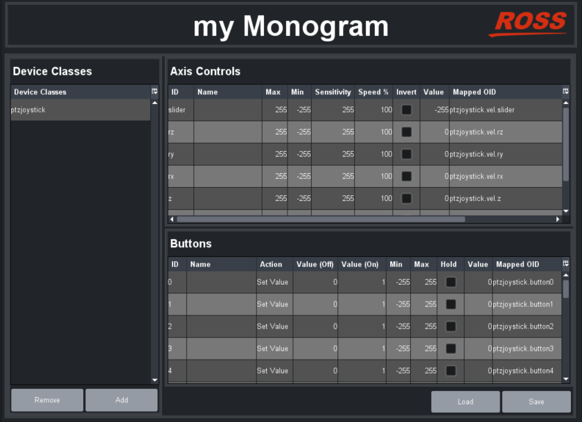
Figure 3 - List of Device Classes, Axis Controls, and Buttons
-
Select Save .
The Save Settings dialog box appears (Figure ??).

Figure 4 - Save Settings Dialog Box
-
Select Save .
The Save File dialog box appears (Figure ??).
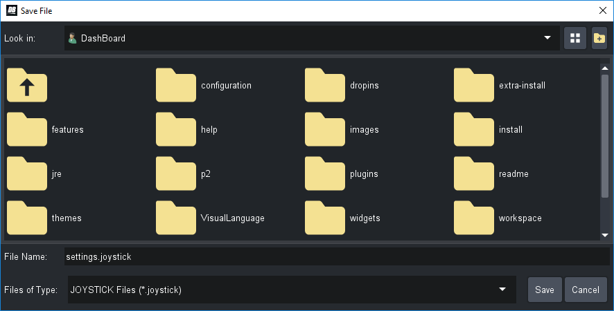
Figure 5 - The Save File Dialog Box
-
Tip : To view the full names of folders and files, select the Details icon (Figure ??) and then expand the Name column.

Figure 6 - The Details Icon (turns blue when Details view is invoked)
-
In the Save File dialog box, navigate to the folder where you want to save the file.
-
In the File Name box, type a name for the file (Figure ??).
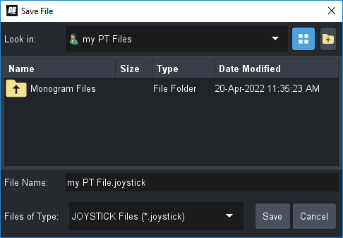
Figure 7 - Specifying a File Name for a DashBoard .joystick File
-
Select Save .
If prompted about replacing an existing file, select Yes if you want to replace the previous version, or select No if you want to specify a different file name.
The Save Settings dialog box reappears (Figure ??).
Figure 8 - Joystick Axis Box
Figure 54 - Restore Settings Dialog Box, with a .joystick File Selected
-
Select Done .
The DashBoard joystick file is saved.
Editing Controls in Monogram Creator
Using Monogram Creator, you can:
-
Swap a function from one control to another.
-
Modify appearance settings, such as halo colors around all controls, and text on the Core module screen).
-
Adjust the velocity sensitivity for some controls, such as Orbiter pad controls (commonly used for pan/tilt).
-
Edit label text for controls. This text appears in Monogram Creator.
How you edit a control depends on whether the control is on a button module (Core or Essential Keys), a Dial module, or an Orbiter module.
This section includes the following topics:
When you edit a configuration profile in Monogram Creator or modify DashBoard joystick settings, the changes persist locally even if you close the applications and restart them, or if you restart the computer. The changes are not automatically saved to the original configuration profile file or DashBoard joystick file. For information about saving settings for future use, see “Save a Configuration Profile and Corresponding a Joystick File”.
Edit Button Controls (Core and Essential Keys)
This section describes how to edit button controls that appear on the Core module and on Essential Keys modules. If you want to edit button controls that appear on a Dial module, see “Edit Dial Module Controls”.
Each button is assigned a button number. These numbers are mapped to parameters in DashBoard. You can configure up to 24 buttons (numbered 0 - 23 ) total. We recommend that you assign each button number to only one button.
To edit button controls:
-
In Monogram Creator, select the button you want to edit.
The Button Settings dialog box appears (Figure ??).
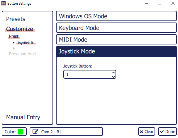
Figure 9 - Button Settings Dialog Box
-
Select Customize .
-
Select Joystick Mode .
tipUse Joystick Mode for all Monogram Creator controls.
-
If you want to change the halo color, select the color swatch you want (Figure ??).

Figure 10 - Color Swatches
-
If you want to edit the label text that appears in Monogram Creator, select the label text box at the bottom left and type the new text (Figure ??).

Figure 11 - Label Text Box
-
If you want to swap functions between two buttons, do the following:
- Record the Joystick Button value of the current (first) button (Figure ??).

Figure 12 - Joystick Button Box
-
In the main Creator dialog, select the button with which you want to swap functions (second button).
-
Record the Joystick Button value.
-
Select the Joystick Button box and then type the value recorded from the first button.
tipYou can configure up to 24 buttons (0 - 23 ). Assign a unique button number to each button.
-
In the Creator dialog, select the first button, and then, in the Joystick Button box, type the value recorded from the second button.
-
Continue editing controls as required. When you are finished, select Done to close the Button Settings dialog box.
-
If you want to use the updated controls in future sessions, save the configuration profile.
For more information, see “Loading and Saving Configuration Profiles and Joystick Files”.
-
Edit Dial Module Controls
This section describes how to edit controls that appear on Dial modules, including dial controls and buttons.
Each axis control, such as a turn dial, Orbiter ring, or Orbiter X-Y pressure pad, is assigned an axis number. These numbers are mapped to parameters in DashBoard. You can configure up to seven axes (numbered 0 - 6 ) total. We recommend that you assign each axis number to only one axis control.
Each button is assigned a button number. These numbers are mapped to parameters in DashBoard. You can configure up to 24 buttons (numbered 0 - 23 ) total. We recommend that you assign each button number to only one button.
To edit Dial module controls:
-
In Monogram Creator, select the dial control you want to edit.
The Dial Settings dialog box appears (Figure ??).
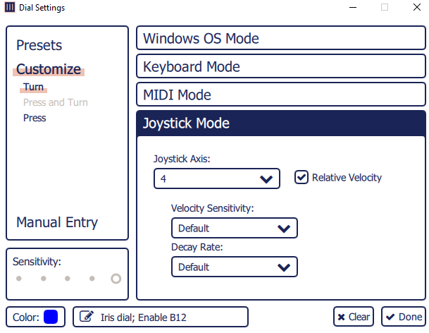
Figure 13 - Dial Settings Dialog Box
-
Select Customize .
-
Select Joystick Mode .
tipUse Joystick Mode for all Monogram Creator controls.
-
If you want to change the halo color, select the color swatch you want (Figure ??).
Figure 14
Figure 60 - Color Swatches
-
If you want to edit the label text that appears in Monogram Creator, select the label text box at the bottom left and type the new text (Figure ??).

Figure 15 - Label Text Box
-
If you want to swap turn-dial functions between two dials, do the following:
-
Select Turn , and then record the settings of the current (first) dial control, including the following:
- Joystick Axis number (Figure ??).
-

Figure 16 - Joystick Axis Box
- Relative Velocity settings (Figure ??).

Figure 17 - Relative Velocity Settings
- Tip : If the Relative Velocity settings are not visible, select the Relative Velocity check box (Figure ??). Always use Relative Velocity mode for turnable axis controls such as turn dials and Orbiter rings.
![]()
Figure 18 - Relative Velocity Check Box
-
Tip : To adjust the responsiveness of the dial to suit your personal preferences, select a different Velocity Sensitivity and/or Decay Rate .
-
In the main Creator dialog, select the dial with which you want to swap functions (second button).
-
Select Customize .
-
Select Joystick Mode .
tipUse Joystick Mode for all Monogram Creator controls.
-
Select Turn , and then record the configured settings (Joystick Axis number and Relative Velocity settings).
-
Configure the settings recorded from the first dial.
-
If you want to swap push-button functions between two dials, do the following:
-
Select Turn .
-
Record the Joystick Button value of the current (first) dial (Figure 12).
-
Figure 19 - Joystick Button Box
-
In the main Creator dialog, select the dial with which you want to swap push-button functions (second dial).
-
Record the Joystick Button value.
-
Select the Joystick Button box and then type the value recorded from the first dial.
tipYou can configure up to 24 buttons (0 - 23 ) total. Assign a unique button number to each button.
-
In the Creator dialog, select the first dial, and then, in the Joystick Button box, type the value recorded from the second dial.
-
Continue editing controls as required. When you are finished, select Done to close the Button Settings dialog box.
-
If you want to use the updated controls in future sessions, save the configuration profile.
For more information, see “Loading and Saving Configuration Profiles and Joystick Files”.
-
Edit Orbiter Module Controls
This section describes how to edit controls that appear on Orbiter modules, including ring controls and X-Y pressure pad controls.
Each axis control, such as a turn dial, Orbiter ring, or Orbiter X-Y pressure pad, is assigned an axis number. These numbers are mapped to parameters in DashBoard. You can configure up to seven axes (numbered 0 - 6 ) total. We recommend that you assign each axis number to only one axis control.
To edit Orbiter module controls:
-
In Monogram Creator, select the Orbiter control you want to edit.
The Orbiter Settings dialog box appears (Figure 13).
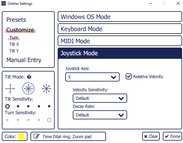
Figure 20 - Orbiter Settings Dialog Box
-
Select Customize .
-
Select Joystick Mode .
tipUse Joystick Mode for all Monogram Creator controls.
-
If you want to change the halo color, select the color swatch you want (Figure ??).
Figure 21
Figure 67 - Color Swatches
-
If you want to edit the label text that appears in Monogram Creator, select the label text box at the bottom left and type the new text (Figure ??).

Figure 22 - Label Text Box
-
If you want to swap ring functions between two Orbiter modules, do the following:
-
Select Turn , and then record the settings of the current (first) ring control, including the following:
- Joystick Axis number (Figure 16).
-
Figure 23
- Relative Velocity settings (Figure 17).
Figure 24 - Relative Velocity Settings
- Tip : If the Relative Velocity settings are not visible, select the Relative Velocity check box (Figure ??). Always use Relative Velocity mode for turnable axis controls such as turn dials and Orbiter rings.
![]()
Figure 25
Figure 71 - Relative Velocity Check Box
-
Tip : To adjust the responsiveness of the Orbiter ring to suit your personal preferences, select a different Velocity Sensitivity and/or Decay Rate .
-
In the main Creator dialog, select the Orbiter with which you want to swap ring functions (second ring control).
-
Select Customize .
-
Select Joystick Mode .
tipUse Joystick Mode for all Monogram Creator controls.
-
Select Turn , and then record the configured settings (Joystick Axis number and Relative Velocity settings).
-
Configure the settings recorded from the first dial.
-
In the Creator dialog, select the first ring, and then configure the settings recorded from the second ring control.
- If you want to swap X-Y pressure pad functions between two Orbiter modules, do the following:
-
Press Tilt X , and then record the Joystick Axis value and whether the axis is inverted (Figure ??) for the current (first) Orbiter module.
-
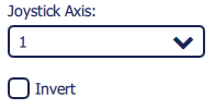
Figure 26 - Joystick Axis Settings
- Repeat this step for the Y axis (Tilt Y ).
- Record the Tilt Sensitivity setting (Figure ??).

Figure 27 - Tilt Sensitivity Setting
-
Tip : You can adjust Tilt Sensitivity to suit your personal preferences.
-
In the main Creator dialog, select the Orbiter module with which you want to swap pressure pad functions (second Orbiter module).
-
Record the Joystick Axis values for both axes (Tilt X and Tilt Y ), and whether the axes are inverted.
-
Record the Tilt Sensitivity setting.
-
Configure the settings recorded from the first Orbiter module.
-
In the Creator dialog, select the first Orbiter module, and then configure the settings recorded from the second Orbiter module.
-
Continue editing controls as required. When you are finished, select Done to close the Button Settings dialog box.
-
If you want to use the updated controls in future sessions, save the configuration profile.
For more information, see “Loading and Saving Configuration Profiles and Joystick Files”.
-
Edit the Core Module Display
You can edit the text and change the icon graphic displayed on the Core module.
To edit the Core module text:
-
In Monogram Creator, double-click the profile tab.
The tab name becomes editable (Figure ??).
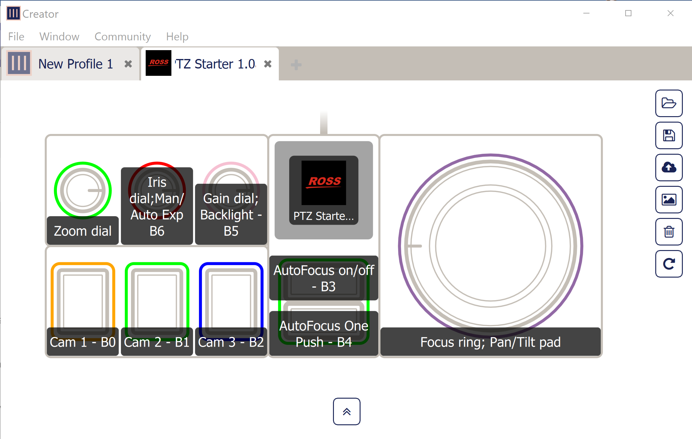
Figure 28 - Editing the Tab Name and Core Module Text
-
Type a new name for the tab, and then press Enter .
The tab name appears on the Core module LCD display.
To change the Core module icon graphic:
-
In Monogram Creator, select the Core module screen.
The Customize Profile Icon dialog box appears. (Figure ??).
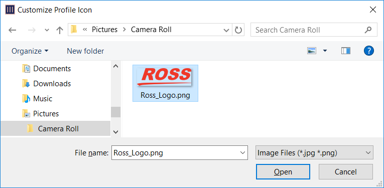
Figure 29 - Customize Profile Icon Dialog Box, with Graphic Selected
-
Navigate to the graphic file you want to display select it, and then select Open .
The graphic appears on the Core module LCD screen. It is automatically rescaled to fit the screen.
tipThe icon graphic file must be either .jpg or .png format. For best results, select a graphic that is approximately square.
Linking Physical Controls to DashBoard Parameters
Monogram Creator works in conjunction with DashBoard to map the Monogram Creator’s physical controls to software controls in DashBoard plugins and DashBoard CustomPanels.
Monogram configuration profile settings assign joystick axis numbers to physical axis controls such as orbiter rings, orbiter pads, and dials, and assign button numbers to physical buttons. DashBoard joystick settings map these numbers to DashBoard parameters, thus enabling you to change DashBoard parameter values in DashBoard plugins and CustomPanels by manipulating physical Monogram controls.
The provided Monogram configuration profiles and corresponding DashBoard joystick files make use of many common DashBoard parameters that control PT heads and PTZ cameras. There are some additional parameters you can map to Monogram controls.
This section describes how to assign axis numbers and button numbers in Monogram Creator, and how to map those numbers to DashBoard parameters in DashBoard. It also includes lists of commonly-used parameters from the PT Head Control plugin and the PTZ Camera Control plugin.
To customize the Monogram Creator, start by loading a configuration profile and joystick file that are appropriate for your Monogram package and the equipment you want to control. For more information, see “Load a Configuration Profile and Corresponding Joystick File”.
This section includes the following major topics:
When you edit a configuration profile in Monogram Creator or modify DashBoard joystick settings, the changes persist locally even if you close the applications and restart them, or if you restart the computer. The changes are not automatically saved to the original configuration profile file or DashBoard joystick file. For information about saving settings for future use, see “Save a Configuration Profile and Corresponding a Joystick File”.
Assign Button Numbers and Axis Numbers in Monogram Creator
This section describes how to assign numbers to Monogram button controls and axis controls. These numbers enable DashBoard to detect the controls.
To assign a button number to a button control:
-
In Monogram Creator, select the button you want to edit.
The Button Settings dialog box appears (Figure ??).
Figure 30 - Button Settings Dialog Box
-
Select Customize , and then click Press .
-
Select Joystick Mode .
tipUse Joystick Mode for all Monogram Creator controls.
-
In the Joystick Button box, select or type the button number you want to assign. (Figure ??).
Figure 31
Figure 77 - Joystick Button Box
- Tip: You can configure up to 24 buttons (0 - 23 ) total. Assign a unique button number to each button.
- Continue editing other properties as required. When you are finished, select Done to close the Button Settings dialog box.
To assign an axis number to an axis control:
-
In Monogram Creator, select the control you want to edit (dial or orbiter).
The settings dialog box for the control appears (Orbiter Settings or Dial Settings ) (Figure ??).
Figure 32 - Orbiter Settings Dialog Box
-
Select Customize .
-
If the control is a dial, select Press .
-
If the control is on an Orbiter module, select the control you want to edit:
- To assign an axis number to the orbiter ring, select Turn .
- To assign an axis number to the X-axis of the orbiter pad, select Tilt X .
- To assign an axis number to the Y-axis of the orbiter pad, select Tilt Y .
-
In the Joystick Axis box, select the axis number you want to assign (Figure ??).
Figure 33
Figure 79 - Joystick Axis Box
-
Note : Each Joystick Axis number must be between 0 and 6 . The total number of axis controls that can be mapped is limited to seven. If you assign a value of 7 to ax axis, that axis is ignored by DashBoard.
-
In the Tilt Mode box, select the Blend Mode you want to assign the Orbiter disc (Figure ??).
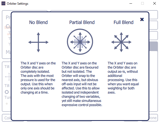
Figure 34 - Blend Modes for Orbiter Disc
-
Continue editing other properties as required. When you are finished, select Done to close thedialog box.
Map Controls to DashBoard Parameters
This section describes how to map controls to DashBoard parameters.
When mapping controls, it is important to understand the properties of the available parameters:
- For information about parameters for the PT Head Control plugin, see “DashBoard Parameters for the DashBoard PT Head Control Plugin”.
- For information about parameters for the PTZ Camera Control plugin, see “DashBoard Parameters for the DashBoard PTZ Camera Control Plugin”.
If you modify DashBoard settings but the control does not behave as expected, sometimes closing and re-opening DashBoard may resolve the issue.
To map controls to DashBoard parameters:
-
In the DashBoard tree, expand the Game Controllers node and then double-click the Monogram Creator’s node(Figure ??).

Figure 35 - Game Controllers Node, with a Monogram Creator Node named my Monogram Highlighted
-
DashBoard configuration settings for the Monogram Creator appear, including lists of Device Classes , Axis Controls , and Buttons (Figure ??).
If the settings do not appear within 20 seconds, close the tab and then double-click the Creative Console’s node again.
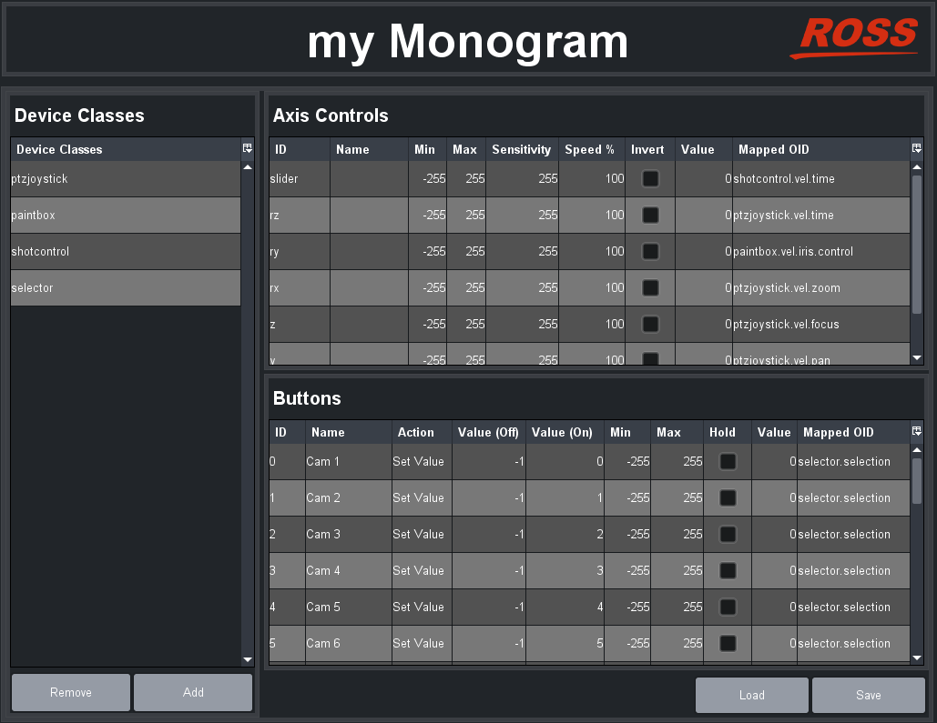
Figure 36 - List of Device Classes, Axis Controls, and Buttons
-
Find the control you want to map by manipulating the physical control while checking for a changing value in the Value column. The row that contains the changing value contains settings for the control.
tipIf the control is an axis control (dial, orbiter ring, or orbiter pad), the axis numbers defined in Monogram Creator are mapped to axis IDs in DashBoard as shown in Table ??.
Table 1 - Monogram Creator Axis Numbers Mapped to DashBoard Axis Control IDs
| Axis Number | Axis ID in DashBoard |
|---|---|
| 6 | slider |
| 5 | rz |
| 4 | ry |
| 3 | rx |
| 2 | z |
| 1 | y |
| 0 | x |
-
If the physical control is an axis control, edit the following columns as required to configure it:
-
ID - The ID of the control, as reported by the controller. This is not configurable.
-
Name - You can name each control for future reference (optional).
-
Min and Max - Defines the range of data values sent to the DashBoard parameter. When the control is in a neutral position, the data value is halfway between Min and Max . For example, if Min is -100 and Max is 200 , the neutral value is 50 .
tipDashBoard automatically scales the data value to suit the data range of the associated parameter. You do not need to match Min and Max to the lowest and highest parameter values.
-
Speed% — Scales the data values, to make them change more or less gradually. For example, if you use a joystick to control a paint velocity parameter such as paintbox.vel.black.master_black , you might set Speed % to 10 . When you push the joystick all the way, the value changes at one-tenth the default rate. This enables you to see the effect more easily as you change the value.
-
Sensitivity — Defines the number of steps between each end of the data range and the controller’s neutral position. For example, if Min is -100 , Max is 100 , and Sensitivity is 20 , then the value changes by increments of 5 . The range of values starts at - 100 (-100 , -95 , -90 , etc.) and continues to 100 .
-
Invert - When selected, reverses the direction of joystick motion required to move the axis. For example, if the PT head and camera are ceiling mounted, select Invert for pan and tilt so when you move the joystick, the head and camera move as desired.
-
Value - Shows the current data value reported by the controller. This is useful for testing.
-
Mapped OID - Specify the parameter OID from the PT Head Control interface to be mapped to the control.
-
-
If the physical control is a button control, edit the following columns as required to configure it:
-
ID - The ID of the control, as reported by the controller. This is not configurable.
noteIf button 22 and/or 23 are assigned in Monogram Creator, the controls appear in DashBoard as buttons 23 and/or 24 , respectively.
-
Name - You can name each control for future reference (optional).
-
Action - The type of action to be performed when the button is pressed.
For information about setting suitable actions for available parameters, see the following:
- PT Head Control plugin parameters — “DashBoard Parameters for the DashBoard PT Head Control Plugin”.
- PTZ Camera Control plugin parameters — “DashBoard Parameters for the DashBoard PTZ Camera Control Plugin”.
-
Value (Off) - The value assigned to the parameter, under the following conditions:
- If Action is set to Toggle , each time the button is pressed the parameter value switches (toggles) between Value (Off) and Value (On) .
- If Action is set to Stateless , Value (Off) is the value of the parameter when the button is released.
- If Action is set to Set Value , Value (Off) is ignored.
- For all other Action settings, Value (Off) is not applicable.
-
Value (On) - The value assigned to the parameter, under the following conditions:
- If Action is set to Toggle , each time the button is pressed the parameter value switches (toggles) between Value (Off) and Value (On) .
- If Action is set to Stateless , Value (On) is the value of the parameter while the button is depressed.
- If Action is set to Set Value , Value (On) is the value assigned to the parameter each time the button is pressed.
- For all other Action settings, Value (On) is not applicable.
-
Value - Shows the current data value reported by the controller. This is useful for testing.
-
Mapped OID - Specify the parameter OID from to be mapped to the control.
-
DashBoard Parameters for the DashBoard PT Head Control Plugin
This section contains the following tables describing parameters for the PT Head Control plugin:
- Table ??
- Table ??
Table 2 - Axis Control Parameters for the PT Head Control Plugin
Table 3 - Button Control Parameters for the PT Head Control Plugin
| Parameter (Mapped OID) | Description |
|---|---|
| selector.selection | Camera system selection, for systems that include multiple cameras/robots. Map this parameter to a set of buttons to be used for selecting the camera system to be controlled. Each row in the Buttons table corresponds to a button on the controller. For each button you want to assign as the selector for a camera system, do the following:
|
| shotcontrol.cut | When pressed, the button performs a Cut action:
|
| shotcontrol.run | When pressed, the button performs a Run action:
|
| shotcontrol.alt | When pressed, the button performs an Alt action:
|
| shotcontrol.halt | When pressed, stops all movement of the PT head and camera controls. To map shotcontrol.halt:
|
| shotcontrol.time.mode | This parameter works in conjunction with the shotcontrol.vel.time parameter, which is an axis parameter that increases/decreases the duration of a preset. The shotcontrol.time.mode parameter enables the operator to choose whether shotcontrol.vel.time applies before the preset runs (alt duration), or while the preset is running (time dilation):
|
| shotcontrol.vel.time | Time axis. This parameter works in conjunction with shotcontrol.time.mode, enabling the controller to change either the duration of a preset before it is recalled (alt duration), or change the speed of robot movement while a preset is being recalled (time dilation). You can configure one or more buttons to apply a speed value to the time axis (value range -100 to 100). To map ptzjoystick.vel.time to a button:
|
| ptzjoystick.vel.tilt | Tilt axis. You can configure one or more buttons to apply a speed value to the tilt axis (value range -100 to 100). To map ptzjoystick.vel.tilt to a button:
|
| ptzjoystick.vel.pan | Pan axis. You can configure one or more buttons to apply a speed value to the pan axis (value range -100 to 100). To map ptzjoystick.vel.pan to a button:
|
| ptzjoystick.vel.zoom | Zoom axis. You can configure one or more buttons to apply a speed value to the zoom axis (value range -100 to 100). To map ptzjoystick.vel.zoom to a button:
|
| ptzjoystick.vel.focus | Focus axis. You can configure one or more buttons to apply a speed value to the focus axis (value range -100 to 100). To map ptzjoystick.vel.focus to a button:
|
| ptzjoystick.vel.time | Time axis. This parameter enables the controller to change the speed of robot movement while a preset is being recalled. To map ptzjoystick.vel.time to a button:
|
| paintbox.iris.control | Iris control. Note: Iris control through the paintbox.iris.contol parameter is available only if the PT head is not configured to control iris through the PTZ page. Configure one button to increase the value and another to decrease it:
|
| ptzjoystick.enable | Enables/disables joystick control of the robot. To map ptzjoystick.enable:
|
DashBoard Parameters for the DashBoard PTZ Camera Control Plugin
This section contains the following tables describing parameters for the PTZ Camera Control plugin:
- Table ??
- Table ??
Table 4 - Axis Control Parameters for the PTZ Camera Control Plugin
Table 5 - Button Control Parameters for the PTZ Camera Control Plugin
Updating Software
From time to time, Ross Video may provide updated versions of software and/or configuration files for your Monogram Creative Console. Updates may include new features and/or security improvements. Such updates and instructions about how to apply them are provided though a set of Monogram Creative Console Configuration Files you can download from the Ross Video website.
We recommend you check for updates occasionally over the life of the product.
This section describes how to check for updates. If updates are available and you want to update your system, it is important to read the Release Notes that come with the Monogram Creative Console Configuration Files , and then follow the instructions in the Updating Software section of the updated edition of this manual.
To check for updates:
-
Navigate to the folder that contains the currently-installed Monogram files (Figure ??).
tiptipBy default, the file path is C:\Ross\Monogram Files .
:::
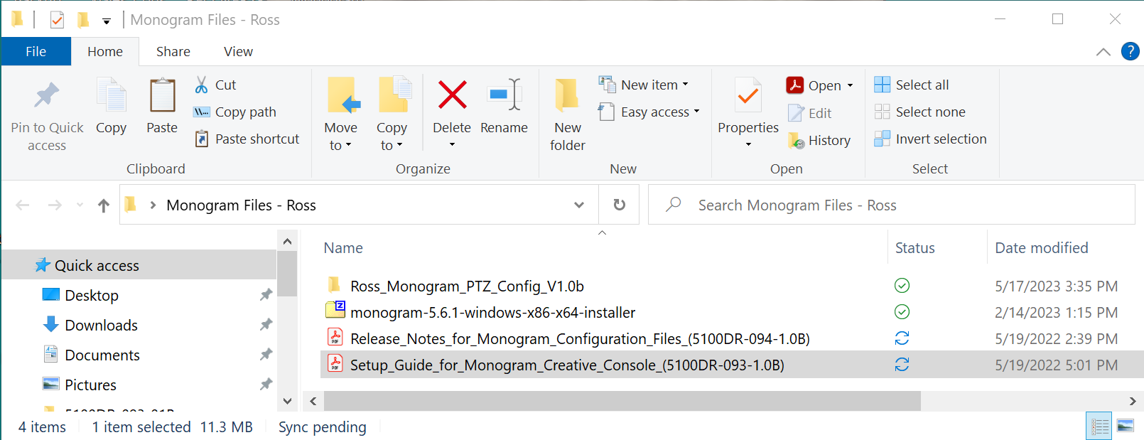
Figure 37 - Monogram Files Folder, showing Current Version Number (in this example, V1.0 b )
-
Note the version number at the end of the folder name. For example, in Figure 37, the version number is V1.0b.
-
In a web browser, navigate to the following URL:
https://www.rossvideo.com/support/software-downloads/robotic-camera-systems/
-
Locate the download link for Monogram Creative Console Configuration Files , and note its version number:
- If the version number for the download link is the same as the version number of the folder on your computer, you have the latest version installed. Skip the remaining steps in this procedure.
- If the version number for the download link is higher than the version number of the folder on your computer, the website download link is for an updated version of the files.
-
If you want to update your Monogram system, download the Monogram Creative Console Configuration Files , and then move the downloaded Ross_Monogram_PTZ_Config_
<version >.zip file from the Downloads folder to the Monogram Files folder (C:\Ross\Monogram Files ). -
Extract the contents of the Ross_Monogram_PTZ_Config_
<version >.zip file into the Monogram Files folder (C:\Ross\Monogram Files ). -
Open and read the document, Release Notes for Monogram Configuration Files (5100DR-094-x.x) .
-
Open the document, Setup Guide for Monogram Creative Console (5100DR-093-x.x) , and follow the instructions in the section, Updating Software .