
Sony®
The information in this document applies to the BRC-H700, BRC-H800, BRC-900, BRC-1000, and EVI-HD1.
Cable Connections
The EVI-HD1, BRC-H700, and BRC-H800 cameras connect to the switcher through a serial connection to a Serial to Ethernet converter (such as the Moxa Nport® 5150A available from Ross®) and then an ethernet connection from the Nport® 5150A to the switcher.
The Moxa Nport® 5150A is a serial to ethernet converter that allows DashBoard and the switcher to connect to a serial device over ethernet, but any serial to ethernet converter device can be used.
The BRC-900 and BRC-1000 cameras connect to the switcher or DashBoard directly through an ethernet connection.
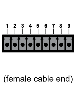
| Carbonite (SERIAL) | BRC-H700 (VISCA RS-422) |
|---|---|
.png)
|
|
| 1 (Tx+) | 6 (Rx+) |
| 2 (Tx-) | 7 (Rx-) |
| 3 (Rx+) | 8 (Tx+) |
| 6 (Rx-) | 9 (Tx-) |
| 7 (GND) | 5 (GND) |
| Carbonite (SERIAL) | BRC-H800 (VISCA IN) |
|---|---|
|
|
|
| 1 (Tx+) | 3 (Rx+) |
| 2 (Tx-) | 6 (Rx-) |
| 3 (Rx+) | 1 (Tx+) |
| 6 (Rx-) | 2 (Tx-) |
| 7 (GND) | 5 (GND) |
EVI-HD1 to Nport® 5150A Cabling
A serial cable is used to connect the EVI-HD1 to the Nport® 5150A. A standard ethernet connection is used between the Nport® 5150A and the switcher.
| EVI-HD1 (VISCA IN) | Nport® 5150A (Port 1) |
|---|---|
.png)
|
.png)
|
| 3 (Tx) | 2 (Rx) |
| 5 (Rx) | 3 (Tx) |
| 4 (GND) | 5 (GND) |
BRC-H700 to Nport® 5150A Cabling
A serial cable is used to connect the BRC-H700 to the Nport® 5150A. A standard ethernet connection is used between the Nport® 5150A and the switcher.
| BRC-H700 (VISCA RS-422) | Nport® 5150A (Port 1) |
|---|---|
|
|
|
| 9 (Tx-) | 4 (Rx-) |
| 6 (Rx+) | 2 (Tx+) |
| 8 (Tx+) | 3 (Rx+) |
| 7 (Rx-) | 1 (Tx-) |
| 5 (GND) | 5 (GND) |
BRC-H800 to Carbonite Cabling
A serial cable is used to connect the BRC-H800 to the switcher.
| BRC-H800 (VISCA RS-422) | Nport® 5150A (Port 1) |
|---|---|
|
|
|
| 2 (Tx-) | 4 (Rx-) |
| 3 (Rx+) | 2 (Tx+) |
| 1 (Tx+) | 3 (Rx+) |
| 6 (Rx-) | 1 (Tx-) |
| 5 (GND) | 5 (GND) |
Switcher Communication Setup
The switcher must be set up to communicate with the robotic camera using specific protocol settings.
To Set Up Serial Communications
- Press MENU > SYSTEM > NEXT > NEXT > Device Config
- Press Add and use the Slot knob to select a serial connection (SP).
- Use the Type knob to select Camera.
- Press NEXT.
- Use the SubType knob to select Sony_1.8.
- Press NEXT.
-
Use the Option and Value knobs to complete the
setup.
Option Value Baud 9600 Parity None - Press the Option knob and Confirm to add the device.
To Set Up Ethernet Communications
- Press MENU > SYSTEM > NEXT > NEXT > Device Config
- Press Add and use the Slot knob to select an ethernet connection (Slot #).
- Use the Type knob to select Camera.
- Press NEXT.
-
Use the SubType knob to select the driver you need to use for your camera.
- Sony Serial to Ethernet Converter — select Sony_1.8
- Sony Direct — select Sony_1.8
- Sony DashBoard Gateway — select PIVOTCam_1.1
- Press NEXT.
-
Use the Field knob to select the segment of the IP address you want to edit and the
Value knob to select the number.
- Sony Serial to Ethernet Converter — the IP address of the Nport® 5150A that you are using to connect to the camera.
- Sony Direct — the IP address of the camera.
- Sony DashBoard Gateway — the IP address of the DashBoard computer.
- Press NEXT.
-
Use the Option and Value knobs to complete the
setup.
Option Value Port - Sony Serial to Ethernet Converter — 4001 (this is the default port assignment on the Nport® 5150A)
- Sony Direct — 52381
- Sony DashBoard Gateway — the port assigned to the camera in the VISCA Gateway on DashBoard
- Press the Option knob and Confirm to add the device.
Switcher Video Setup
The switcher must be set up to associate the camera controls with the video source coming into the switcher. When you select the source coming from the camera on a bus, the menu jumps to the camera controls for that camera.
To Assign a Camera to a Video Input
- Press MENU > CONFIG > Input > NEXT.
- Use the Input knob to select the input BNC that is connected to the camera.
- Press the Device knob.
- Use the Device knob to select the camera you set up for the input BNC.
- Press NEXT.
-
Use the Option and Value knobs to complete the
setup.
Option Value Channel Select the channel, or address, that the particular camera head you want to control is on. Invert Tilt Tilt control using the positioner is inverted (Yes) or not (No). Invert Pan Pan control using the positioner is inverted (Yes) or not (No). - Press the Option knob and Confirm to add the device.
Nport® 5150A Setup
Refer to the documentation that came with your Nport® 5150A for safety and setup information.
Use the NPort Administrator application to set up the Nport® 5150A as listed below.
Operation Mode
- Operation Mode — TCP Server Mode
- Max Connection — 2 (or more)
Serial Parameters
- Baudrate — 9600
- Data bits — 8
- Stop bits — 1
- Parity — None
- Flow control — RTS/CTS
- FIFO — Enable
- Interface — RS-232 (EVI-HD1), or RS-422 (BRC-H700/BRC-H800)
Ethernet Parameters
- IP Address — the default IP address is shown on the bottom of the device
- Local TCP Port — 4001 (default)
EVI-HD1 Setup
The jumpers on the EVI-HD1 that is connected to the switcher must be set as follows:
| Jumper | Value |
|---|---|
| 1 | Infra-red signal control (OFF) disables the control |
| 2 | Set to OFF for 9600 baud rate |
| 3 | No connection |
| 4 | No connection |
If you are daisy chaining multiple EVI-HD1 Robotic Cameras together, use the following pinouts to connect the one camera to the next.
| VISCA Out | VISCA In |
|---|---|
| 1 (DTR) | 2 (DSR) |
| 2 (DSR) | 1 (DTR) |
| 3 (Tx) | 5 (Rx) |
| 4 (Gnd) | 4 (Gnd) |
| 5 (Rx) | 3 (Tx) |
BRC-H700 Setup
The jumpers on the BRC-H700 that is connected to the switcher must be set as follows:
| Switch | Value |
|---|---|
| 1 | No connection |
| 2 | Set to ON for RS-422 communications |
| 3 | Set to OFF for 9600 baud rate |
| 4 | Infra-red signal control (OFF) disables the control |
| Camera Address | 1 | 2 | 3 | 4 | 5 | 6 | 7 |
|---|---|---|---|---|---|---|---|
| Switch 1 | ON | OFF | ON | OFF | ON | OFF | ON |
| Switch 2 | OFF | ON | ON | OFF | OFF | ON | ON |
| Switch 3 | OFF | OFF | OFF | ON | ON | ON | ON |
| Switch 4 | not used | ||||||
If you are daisy chaining multiple BRC-H700 Robotic Cameras together, use the following pinouts to connect the one camera to the next.
| VISCA Out | VISCA In |
|---|---|
| 1 (DTR) | 2 (DSR) |
| 2 (DSR) | 1 (DTR) |
| 3 (Tx) | 5 (Rx) |
| 4 (Gnd) | 4 (Gnd) |
| 5 (Rx) | 3 (Tx) |
BRC-H800 Setup
The DIP switches on the BRC-H800 that is connected to the switcher must be set as follows:
| Switch | Value |
|---|---|
| 1 | Set to OFF for Level A in 3G-SDI |
| 2 | reserved |
| 3 | reserved |
| 4 | Set to OFF for 9600 baud rate |
| 5/6/7 | Use for camera address |
| Camera Address | Auto | 1 | 2 | 3 | 4 | 5 | 6 | 7 |
|---|---|---|---|---|---|---|---|---|
| Switch 5 | OFF | ON | OFF | ON | OFF | ON | OFF | ON |
| Switch 6 | OFF | OFF | ON | ON | OFF | OFF | ON | ON |
| Switch 7 | OFF | OFF | OFF | OFF | ON | ON | ON | ON |
If you are daisy chaining multiple BRC-H800 Robotic Cameras together, use a standard ethernet cable to connect VISCA OUT on one camera to the VISCA IN on the next.
DashBoard Gateway Setup
Before setting up the gateway, you must set up control of the VISCA camera in DashBoard. Refer to the DashBoard documentation for information on controlling a camera from DashBoard.
- On the camera tab in DashBoard, click Config > Gateway.
- In the Port field, enter the port number you want to use to control the camera from the switcher. This is the port number that you will enter in the device setup on the switcher.
- Select what control you want the gateway to pass on to the camera from the switcher.
- Focus Mode — select whether the gateway passes focus mode selections made from the switcher on to
the camera (Pass), or if the gateway blocks these messages (Block). An
external controller can still read the current focus mode when set to Block.Tip: The switcher automatically sets and updates the focus mode when controlling the camera. This can prevent other controllers from changing the focus mode when the switcher is controlling the camera and the Focus Mode is set to Pass.
- Presets — select whether the gateway stores camera shots on the camera
(Camera), or on the DashBoard computer
(Local).Tip: If you store the presets locally on the DashBoard computer they are also available to the camera control interface in DashBoard on the same computer.
- Focus Mode — select whether the gateway passes focus mode selections made from the switcher on to
the camera (Pass), or if the gateway blocks these messages (Block). An
external controller can still read the current focus mode when set to Block.
- Click a Control button to allow the switcher to use the gateway to control the camera (Enable) or block the switcher from controlling the camera through the gateway (Disable).
The Status field shows the current state of the gateway.
- Closed — the port is closed or DashBoard isn't connect to the camera.
- Ready — the port is open, but there are no controllers currently connected to it.
- Connected — the port is open and one or more controllers are connected to it.
- Error — an error has occurred. The port may be used by a different service or is being used by a different gateway.