
NK Series Auxiliary Control Panels
The information in this document applies to the RCP-NK1 and NK-IPS.
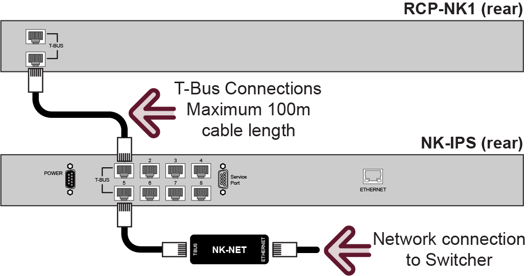
Cable Connections
The Ross® RCP-NK1 connects to the switcher through an NK-IPS and NK-NET. The connection between the NK-NET and the switcher is over ethernet.
Refer to the documentation that came with your device for safety and setup information.
Switcher Communications Setup
The switcher must be set up to communicate with the aux panel using an ethernet protocol.
To Set Up Ethernet Communications
- Press MENU > SYSTEM > NEXT > NEXT > Device Config
- Press Add and use the Slot knob to select an ethernet connection (Slot #).
- Use the Type knob to select RouterPanel.
- Press NEXT.
- Use the SubType knob to select NK-IPS_1.0.
- Press NEXT.
-
Use the Field knob to select the segment of the IP address you want to edit and the
Value knob to select the number.
Note: You must enter the IP address of the NK-NET that you are using to communicate with the NK-IPS.
- Press NEXT.
-
Use the Option and Value knobs to complete the
setup.
Option Value Port Select the Client TCP Port of the NK-IPS that the RCP-NK1 is connected to. Level Select which level on the RCP panel is controlling the switcher. - Press the Option knob and Confirm to add the device.
Auxiliary Control Panel Setup
The aux panel must be set up to communicate with the switcher using the same communications as you set the switcher up to use.
To Set Up Ethernet Communications
The information in this procedure is provided as a guide and may not represent the current state of the RCP panels. Refer to the documentation that came with your RCP panel for the latest setup information.
- Connect the RCP to a network on the same subnet as your DashBoard computer and the switcher.
- In DashBoard, click File > Show Walkabout.
-
Click Refresh.
A list of all RCP panels on the network is shown.
-
Select the RCP panel that you want to set up.
Tip: If you do not know which RCP is the one you want to set up, click Locate for each RCP until the buttons on your RCP panel start flashing. Click Locate again to stop the buttons flashing.
-
Enter the IP Address (Address), netmask (Netmask), and
gateway (Gateway) you want to assign to the panel.
Tip: You can also enter a name (Name) for the panel if you want.
-
Click Reboot to reboot the panel and apply the new network settings.
When the panel reboots with the new network settings it should be discovered by DashBoard and appear in the Basic Tree View.
- Double-click the RCP node in the Basic Tree View to open the configuration window.
- In the Servers to connect to area, enter the IP address of the NK-IPS that you want to connect it to.
- Click Send Configuration.
Remote Control Panel Interface
From the Ross RCP-NK1 Remote Panel, you can select video sources on Aux, Program, Preview, and Key buses on the switcher, and run custom controls.
To Select a Source on a Bus from the Remote Panel
- Select the level on the Remote Control Panel that is assigned to the switcher.
- Select the button on the output section of the Remote Panel that corresponds to the output BNC on the switcher. Refer to the output mapping table for your switcher.
- Select the button on the input section of the Remote Panel that corresponds to the source on the switcher you want to select. Refer to the input mapping table for your switcher.
Selecting an input (or source) on the Remote Panel acts like a selection of that source on the bus of the switcher.
Router Panel Output/Input Mapping
| Router Output | Carbonite | Graphite | Carbonite Black SD/HD | Ultra SD/HD | Carbonite Black UHDTV1 | Ultra UHDTV1 |
|---|---|---|---|---|---|---|
| 1-8 | Aux 1-8 | |||||
| 9-10 | -- | Aux 9-10 | ||||
| 11-20 | -- | Aux 11-20 | -- | Aux 11-20 | ||
| 21-28 | -- | Aux 21-28 | -- | Aux 21-28 | ||
| 61 | MiniME™ 1 Program | |||||
| 62 | MiniME™ 1 Preview | |||||
| 63 | MiniME™ 1 Key 1 Video+Alpha | |||||
| 64 | MiniME™ 1 Key 2 Video+Alpha | |||||
| 65 | MiniME™ 1 Key 1 Alpha | |||||
| 66 | MiniME™ 1 Key 2 Alpha | |||||
| 67 | MiniME™ 2 Program | |||||
| 68 | MiniME™ 2 Preview | |||||
| 69 | MiniME™ 2 Key 1 Video+Alpha | |||||
| 70 | MiniME™ 2 Key 2 Video+Alpha | |||||
| 71 | MiniME™ 2 Key 1 Alpha | |||||
| 72 | MiniME™ 2 Key 2 Alpha | |||||
| 73 | MiniME™ 3 Program | -- | ||||
| 74 | MiniME™ 3 Preview | -- | ||||
| 75 | MiniME™ 3 Key 1 Video+Alpha | -- | ||||
| 76 | MiniME™ 3 Key 2 Video+Alpha | -- | ||||
| 77 | MiniME™ 3 Key 1 Alpha | -- | ||||
| 78 | MiniME™ 3 Key 2 Alpha | -- | ||||
| 79 | MiniME™ 4 Program | -- | ||||
| 80 | MiniME™ 4 Preview | -- | ||||
| 81 | MiniME™ 4 Key 1 Video+Alpha | -- | ||||
| 82 | MiniME™ 4 Key 2 Video+Alpha | -- | ||||
| 83 | MiniME™ 4 Key 1 Alpha | -- | ||||
| 84 | MiniME™ 4 Key 2 Alpha | -- | ||||
| 85 | MultiScreen/CanvasMultiScreenMultiScreen 1 Program | -- | CanvasMultiScreenMultiScreen 1 Program | |||
| 86 | MultiScreen/CanvasMultiScreenMultiScreen 1 Preview | -- | CanvasMultiScreenMultiScreen 1 Preview | |||
| 87 | MultiScreen/CanvasMultiScreenMultiScreen 1 Key 1 Video+Alpha | -- | CanvasMultiScreenMultiScreen 1 Key 1 Video+Alpha | |||
| 88 | MultiScreen/CanvasMultiScreenMultiScreen 1 Key 2 Video+Alpha | -- | CanvasMultiScreenMultiScreen 1 Key 2 Video+Alpha | |||
| 89 | MultiScreen/CanvasMultiScreenMultiScreen 1 Key 1 Alpha | -- | CanvasMultiScreenMultiScreen 1 Key 1 Alpha | |||
| 90 | MultiScreen/CanvasMultiScreenMultiScreen 1 Key 2 Alpha | -- | CanvasMultiScreenMultiScreen 1 Key 2 Alpha | |||
| 91 | MultiScreen/CanvasMultiScreenMultiScreen 2 Program | -- | ||||
| 92 | MultiScreen/CanvasMultiScreenMultiScreen 2 Preview | -- | ||||
| 93 | MultiScreen/CanvasMultiScreenMultiScreen 2 Key 1 Video+Alpha | -- | ||||
| 94 | MultiScreen/CanvasMultiScreenMultiScreen 2 Key 2 Video+Alpha | -- | ||||
| 95 | MultiScreen/CanvasMultiScreenMultiScreen 2 Key 1 Alpha | -- | ||||
| 96 | MultiScreen/CanvasMultiScreenMultiScreen 2 Key 2 Alpha | -- | ||||
| 97 | PGM ME Program | ME P/P Program | PGM ME Program | ME P/P Program | ||
| 98 | PGM ME Preview | ME P/P Preview | PGM ME Preview | ME P/P Preview | ||
| 99 | PGM ME Key 1 Video+Alpha | ME P/P Key 1 Video+Alpha | PGM ME Key 1 Video+Alpha | ME P/P Key 1 Video+Alpha | ||
| 100 | PGM ME Key 2 Video+Alpha | ME P/P Key 2 Video+Alpha | PGM ME Key 2 Video+Alpha | ME P/P Key 2 Video+Alpha | ||
| 101 | PGM ME Key 3 Video+Alpha | ME P/P Key 3 Video+Alpha | PGM ME Key 3 Video+Alpha | ME P/P Key 3 Video+Alpha | ||
| 102 | PGM ME Key 4 Video+Alpha | ME P/P Key 4 Video+Alpha | PGM ME Key 4 Video+Alpha | ME P/P Key 4 Video+Alpha | ||
| 105 | PGM ME Key 1 Alpha | ME P/P Key 1 Alpha | PGM ME Key 1 Alpha | ME P/P Key 1 Alpha | ||
| 106 | PGM ME Key 2 Alpha | ME P/P Key 2 Alpha | PGM ME Key 2 Alpha | ME P/P Key 2 Alpha | ||
| 107 | PGM ME Key 3 Alpha | ME P/P Key 3 Alpha | PGM ME Key 3 Alpha | ME P/P Key 3 Alpha | ||
| 108 | PGM ME Key 4 Alpha | ME P/P Key 4 Alpha | PGM ME Key 4 Alpha | ME P/P Key 4 Alpha | ||
| 111 | ME 1 Program | |||||
| 112 | ME 1 Preview | |||||
| 113 | ME 1 Key 1 Video+Alpha | |||||
| 114 | ME 1 Key 2 Video+Alpha | |||||
| 115 | ME 1 Key 3 Video+Alpha | |||||
| 116 | ME 1 Key 4 Video+Alpha | |||||
| 119 | ME 1 Key 1 Alpha | |||||
| 120 | ME 1 Key 2 Alpha | |||||
| 121 | ME 1 Key 3 Alpha | |||||
| 122 | ME 1 Key 4 Alpha | |||||
| 125 | ME 2 Program | -- | ||||
| 126 | ME 2 Preview | -- | ||||
| 127 | ME 2 Key 1 Video+Alpha | -- | ||||
| 128 | ME 2 Key 2 Video+Alpha | -- | ||||
| 129 | ME 2 Key 3 Video+Alpha | -- | ||||
| 130 | ME 2 Key 4 Video+Alpha | -- | ||||
| 133 | ME 2 Key 1 Alpha | -- | ||||
| 134 | ME 2 Key 2 Alpha | -- | ||||
| 135 | ME 2 Key 3 Alpha | -- | ||||
| 136 | ME 2 Key 4 Alpha | -- | ||||
| 139 | ME 3 Program | -- | ME 3 Program | -- | -- | -- |
| 140 | ME 3 Preview | -- | ME 3 Preview | -- | -- | -- |
| 141 | ME 3 Key 1 Video+Alpha | -- | ME 3 Key 1 Video+Alpha | -- | -- | -- |
| 142 | ME 3 Key 2 Video+Alpha | -- | ME 3 Key 2 Video+Alpha | -- | -- | -- |
| 143 | -- | -- | ME 3 Key 3 Video+Alpha | -- | -- | -- |
| 144 | -- | -- | ME 3 Key 4 Video+Alpha | -- | -- | -- |
| 147 | ME 3 Key 1 Alpha | -- | ME 3 Key 1 Alpha | -- | -- | -- |
| 148 | ME 3 Key 2 Alpha | -- | ME 3 Key 2 Alpha | -- | -- | -- |
| 149 | -- | -- | ME 3 Key 3 Alpha | -- | -- | -- |
| 150 | -- | -- | ME 3 Key 4 Alpha | -- | -- | -- |
| 167 | -- | -- | -- | CK1 Video | ||
| 168 | -- | -- | -- | CK2 Video | ||
| 169 | -- | -- | -- | CK3 Video | -- | -- |
| 170 | -- | -- | -- | CK4 Video | -- | -- |
| Router Input | Carbonite | Graphite | Carbonite Black SD/HD | Ultra SD/HD | Carbonite Black UHDTV1 | Ultra UHDTV1 |
|---|---|---|---|---|---|---|
| 1-9 | Input 1-9 | |||||
| 10-13 | Input 10-13 | -- | Input 10-13 | |||
| 14-24 | Input 14-24 | -- | Input 14-24 | -- | Input 14-24 | |
| 25-36 | -- | -- | Input 25-36 | -- | -- | -- |
| 149 | Media-Store 1 | |||||
| 150 | Media-Store 2 | |||||
| 151 | Media-Store 3 | -- | -- | |||
| 152 | Media-Store 4 | -- | -- | |||
| 153 | -- | Media-Store 1 Alpha | -- | Media-Store 1 Alpha | ||
| 154 | -- | Media-Store 2 Alpha | -- | Media-Store 2 Alpha | ||
| 155 | -- | Media-Store 3 Alpha | -- | -- | ||
| 156 | -- | Media-Store 4 Alpha | -- | -- | ||
| 169 | Black | |||||
| 170 | Matte | |||||
| 171 | -- | Clip Player | -- | Clip Player | ||
| 176 | PGM ME Program | ME P/P Program | PGM ME Program | ME P/P Program | ||
| 177 | PGM ME Preview | ME P/P Preview | PGM ME Preview | ME P/P Preview | ||
| 178 | PGM ME Clean Feed | ME P/P Clean Feed | PGM ME Clean Feed | ME P/P Clean Feed | ||
| 180 | ME 1 Program | |||||
| 181 | ME 1 Preview | |||||
| 182 | ME 1 Clean Feed | |||||
| 184 | ME 2 Program | -- | -- | |||
| 185 | ME 2 Preview | -- | -- | |||
| 186 | ME 2 Clean Feed | -- | -- | |||
| 188 | ME 3 Program | -- | -- | -- | ||
| 189 | ME 3 Preview | -- | -- | -- | ||
| 190 | ME 3 Clean Feed | -- | -- | -- | ||
| 200 | -- | -- | -- | CK 1 Video | ||
| 201 | -- | -- | -- | CK 1 Alpha | ||
| 202 | -- | -- | -- | CK 2 Video | ||
| 203 | -- | -- | -- | CK 2 Alpha | ||
| 204 | -- | -- | -- | CK 3 Video | -- | -- |
| 205 | -- | -- | -- | CK 3 Alpha | -- | -- |
| 206 | -- | -- | -- | CK 4 Video | -- | -- |
| 207 | -- | -- | -- | CK 4 Alpha | -- | -- |
| 208 | MiniME™ 1 | MiniME™ 1 | MiniME™ 1 | MiniME™ 1 | ||
| 209 | MiniME™ 2 | MiniME™ 1 PV | MiniME™ 2 | MiniME™ 1 PV | ||
| 210 | MiniME™ 3 | MiniME™ 2 | -- | MiniME™ 2 | ||
| 211 | MiniME™ 4 | MiniME™ 2 PV | -- | MiniME™ 2 PV | ||
| 212 | ME 1 MediaWipe Video | MiniME™ 3 | ME 1 MediaWipe Video | -- | ||
| 213 | ME 1 MediaWipe Alpha | MiniME™ 3 PV | ME 1 MediaWipe Alpha | -- | ||
| 214 | ME 2 MediaWipe Video | MiniME™ 4 | ME 2 MediaWipe Video | -- | ||
| 215 | ME 2 MediaWipe Alpha | MiniME™ 4 PV | ME 2 MediaWipe Alpha | -- | ||
| 216 | MultiViewer 1 | -- | -- | ME P/P MediaWipe Video | -- | ME P/P MediaWipe Video |
| 217 | MultiViewer 2 | -- | -- | ME P/P MediaWipe Alpha | -- | ME P/P MediaWipe Alpha |
| 218 | Aux 1 | ME 1 MediaWipe Video | Aux 1 | ME 1 MediaWipe Video | ||
| 219 | Aux 2 | ME 1 MediaWipe Alpha | Aux 2 | ME 1 MediaWipe Alpha | ||
| 220 | Aux 3 | ME 2 MediaWipe Video | Aux 3 | -- | ||
| 221 | Aux 4 | ME 2 MediaWipe Alpha | Aux 4 | -- | ||
| 222 | Aux 5 | Aux 1 | Aux 5 | Aux 1 | ||
| 223 | Aux 6 | Aux 2 | Aux 6 | Aux 2 | ||
| 224 | Aux 7 | Aux 3 | Aux 7 | Aux 3 | ||
| 225 | Aux 8 | Aux 4 | Aux 8 | Aux 4 | ||
| 226 | Aux 9 | Aux 5 | Aux 9 | Aux 5 | ||
| 227 | Aux 10 | Aux 6 | Aux 10 | Aux 6 | ||
| 228 | Aux 11 | Aux 7 | Aux 11 | Aux 7 | ||
| 229 | Aux 12 | Aux 8 | Aux 12 | Aux 8 | ||
| 230 | Aux 13 | Aux 9 | Aux 13 | Aux 9 | ||
| 231 | Aux 14 | Aux 10 | Aux 14 | Aux 10 | ||
| 232 | Aux 15 | Aux 11 | Aux 15 | Aux 11 | ||
| 233 | Aux 16 | Aux 12 | Aux 16 | Aux 12 | ||
| 234 | Aux 17 | Aux 13 | Aux 17 | Aux 13 | ||
| 235 | Aux 18 | Aux 14 | Aux 18 | Aux 14 | ||
| 236 | Aux 19 | Aux 15 | Aux 19 | Aux 15 | ||
| 237 | Aux 20 | Aux 16 | Aux 20 | Aux 16 | ||
| 238 | -- | Aux 17 | -- | Aux 17 | ||
| 239 | -- | Aux 18 | -- | Aux 18 | ||
| 240 | -- | Aux 19 | -- | Aux 19 | ||
| 241 | -- | Aux 20 | -- | Aux 20 | ||
| 242 | -- | Aux 21 | -- | Aux 21 | ||
| 243 | -- | Aux 22 | -- | Aux 22 | ||
| 244 | -- | Aux 23 | -- | Aux 23 | ||
| 245 | -- | Aux 24 | -- | Aux 24 | ||
| 246 | -- | Aux 25 | -- | Aux 25 | ||
| 247 | -- | Aux 26 | -- | Aux 26 | ||
| 248 | -- | Aux 27 | -- | Aux 27 | ||
| 249 | -- | Aux 28 | -- | Aux 28 | ||
| 278 | -- | XPression Channel 1 Video1 | -- | -- | -- | -- |
| 279 | -- | XPression Channel 1 Alpha1 | -- | -- | -- | -- |
| 280 | -- | XPression Channel 2 Video1 | -- | -- | -- | -- |
| 281 | -- | XPression Channel 2 Alpha1 | -- | -- | -- | -- |
| 282 | -- | XPression Channel 3 Video1 | -- | -- | -- | -- |
| 283 | -- | XPression Channel 3 Alpha1 | -- | -- | -- | -- |
| 284 | -- | XPression Channel 4 Video1 | -- | -- | -- | -- |
| 285 | -- | XPression Channel 4 Alpha1 | -- | -- | -- | -- |
1 Graphite only
To Run, Stop, or Resume a Custom Control from a Remote Panel
- Select the level on the Remote Control Panel that is assigned to the switcher.
- Select the button on the output section of the Remote Panel that corresponds to the custom control bank that you want to run, stop, or resume a custom control on. Refer to the following tables for bank mapping information.
- Select the button on the input section of the Remote Panel that corresponds to the custom control that you want to run, stop, or resume. Refer to the following table for custom control mapping.
Router Panel CC Mapping
| Router Output | Switcher Source |
|---|---|
| 223 | Custom Control Bank 1 |
| 224 | Custom Control Bank 2 |
| 225 | Custom Control Bank 3 |
| 226 | Custom Control Bank 4 |
| 227 | Custom Control Bank 5 |
| 228 | Custom Control Bank 6 |
| 229 | Custom Control Bank 7 |
| 230 | Custom Control Bank 8 |
| Router Input | Switcher Source |
|---|---|
| 1-32 | Custom Controls |
| Router Input | Switcher Source |
|---|---|
| 1-40 | Custom Controls |