
Ross® PIVOTCam
The information in this document applies to the PIVOTCam-20 and PIVOTCam-SE.
Cable Connections
Cable connections to the PIVOTCam depend on the model of PIVOTCam you have.
PIVOTCam-20
To control the camera from the switcher and/or DashBoard you must connect a serial cable to the 8-Pin Mini-DIN RS232 IN port on the camera to a Serial to Ethernet converter (such as the Moxa Nport® 5150A available from Ross®) and then an ethernet connection from the Nport® 5150A to the switcher and/or DashBoard.
The Moxa Nport® 5150A is a serial to ethernet converter that allows DashBoard and the switcher to connect to a serial device over ethernet, but any serial to ethernet converter device can be used.
PIVOTCam-SE
To control the PIVOTCam-SE from the switcher and/or DashBoard you must connect an ethernet cable to the LAN port on the camera that is connected to the same subnet as the switcher and/or DashBoard. You must connect on port 52381 for direct control from the switcher.
PIVOTCam to Nport® 5150A Cabling
A serial cable (RS-232 Control Cable provided with camera) is used to connect the PIVOTCam to the Nport® 5150A. A standard ethernet connection is used between the Nport® 5150A and the switcher.
| PIVOTCam (RS232 IN) | Nport® 5150A (Port 1) |
|---|---|
.png)
|
.png)
|
| 3 (Tx) | 2 (Rx) |
| 5 (Rx) | 3 (Tx) |
| 4 (GND) | 5 (GND) |
Switcher Communication Setup
The switcher must be set up to communicate with the robotic camera using specific protocol settings.
To Set Up Ethernet Communications
-
Click Navigation Menu > Configuration > Devices.
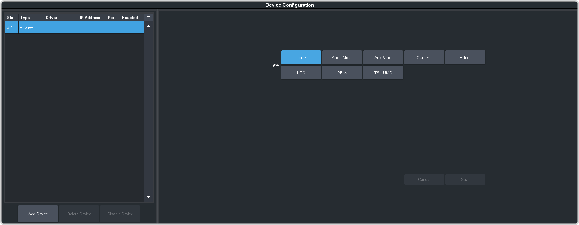
-
Click Add Device.
Tip: Click Disable Device to temporarily disable the selected device.
-
Click Slot and select a free ethernet device slot.
Tip: A slot does not appear in the list if it is being used. You can click on the slot in the table on the left to edit the device settings.
-
In the Type area click Camera.
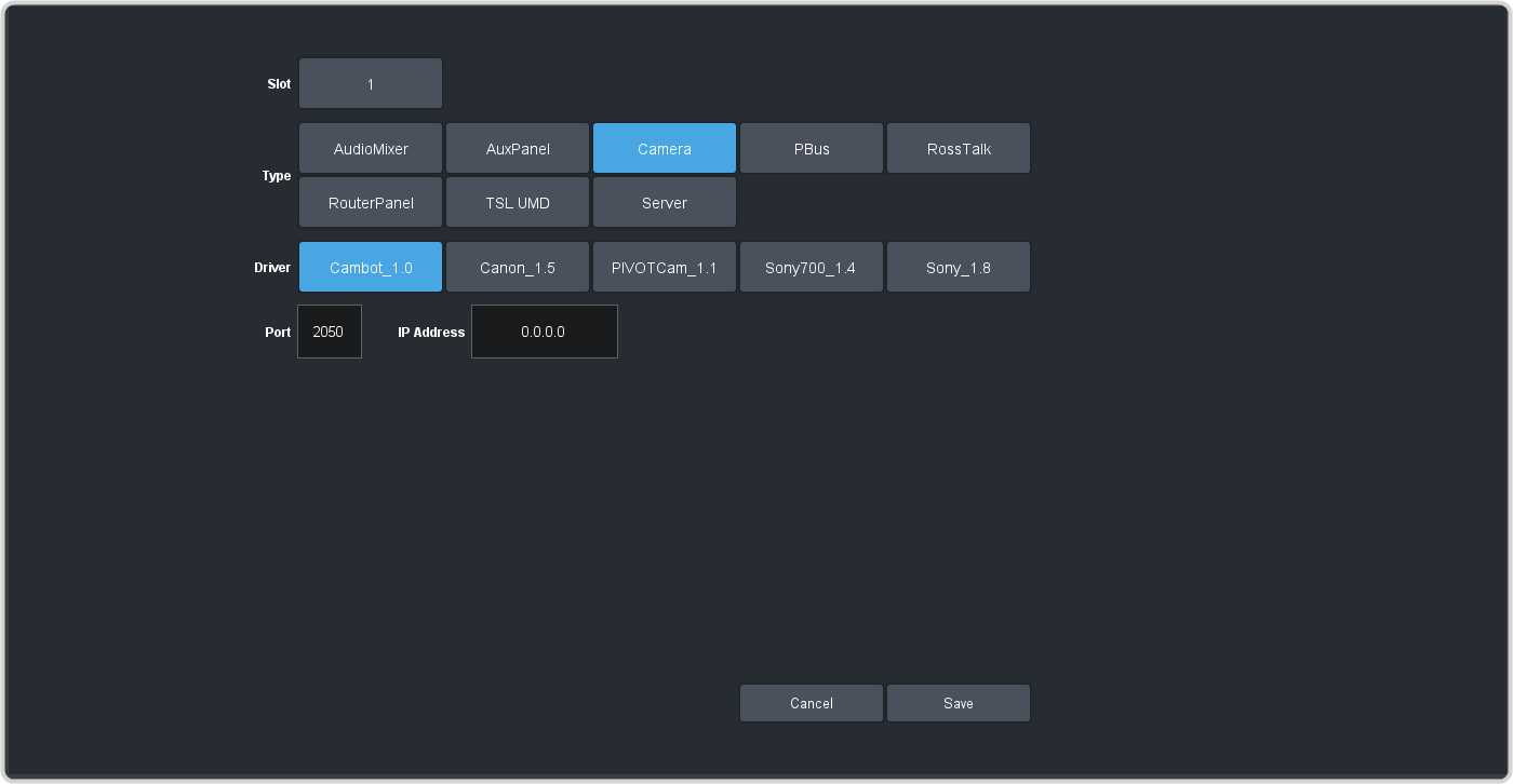
-
Select the following setting for your device:
Setting Selection Driver PIVOTCam_1.1 IP Address - PIVOTCam-20 — the IP address of the Nport® 5150A that you are using to connect to the camera.
- PIVOTCam-SE Direct — the IP address of the PIVOTCam-SE.
- PIVOTCam-SE DashBoard Gateway — the IP address of the DashBoard computer.
Port - PIVOTCam-20 — 4001 (this is the default port assignment on the Nport® 5150A)
- PIVOTCam-SE Direct — 52381
- PIVOTCam-SE DashBoard Gateway — the port assigned to the camera in the VISCA Gateway on DashBoard
- Click Save.
Switcher Video Setup
The switcher must be set up to associate the camera controls with the video source coming into the switcher. When you select the source coming from the camera on a bus, the menu jumps to the camera controls for that camera.
To Assign a Camera to a Video Input
-
Click Navigation Menu > Configuration > Inputs > External.
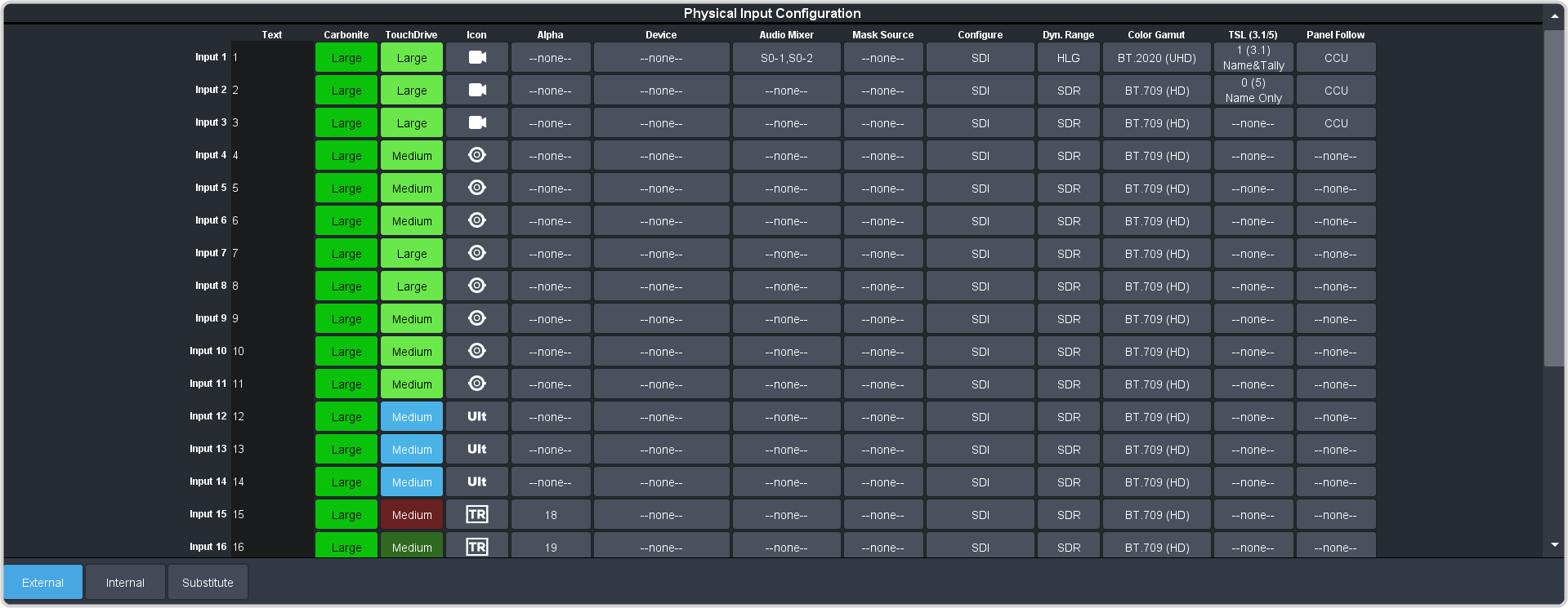
-
Click the Device button for the video source that you want to assign a device to.
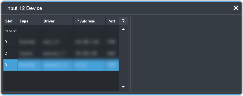
- Click the device you want to assign to the video source.
-
Select the following setting for your device:
Option Value Channel Select the channel, or address, that the particular camera head you want to control is on. Invert Pan Pan control using the positioner is inverted (Yes) or not (No). Invert Tilt Tilt control using the positioner is inverted (Yes) or not (No).
Nport® 5150A Setup
Refer to the documentation that came with your Nport® 5150A for safety and setup information.
Use the NPort Administrator application to set up the Nport® 5150A as listed below.
Operation Mode
- Operation Mode — TCP Server Mode
- Max Connection — 2 (or more)
Serial Parameters
- Baud rate — 9600
- Data bits — 8
- Stop bits — 1
- Parity — None
- Flow control — RTS/CTS
- FIFO — Enable
- Interface — RS-232
Ethernet Parameters
- IP Address — the default IP address is shown on the bottom of the device
- Local TCP Port — 4001 (default)
Robotic Camera Setup
PIVOTCam-20
On the PIVOTCam-20, the following changes must be made on the SYSTEM menu:
- PROTOCOL — set to VISCA
- RS485 — set to OFF
- BAUD RATE — set to 9600
PIVOTCam-SE
On the PIVOTCam-SE, the following changes must be made on the SYSTEM menu:
- PROTOCOL — set to VISCA
- VISCA — set to OVER IP for ethernet control
Daisy Chaining
If you are daisy chaining multiple PIVOTCam cameras together, use the following pinouts to connect the one camera to the next.
| RS232 Out | RS232 In |
|---|---|
| 1 (DTR) | 2 (DSR) |
| 2 (DSR) | 1 (DTR) |
| 3 (Tx) | 5 (Rx) |
| 4 (Gnd) | 4 (Gnd) |
| 5 (Rx) | 3 (Tx) |
DashBoard Gateway Setup
Before setting up the gateway, you must set up control of the VISCA camera in DashBoard. Refer to the DashBoard documentation for information on controlling a camera from DashBoard.
- On the camera tab in DashBoard, click Config > Gateway.
- In the Port field, enter the port number you want to use to control the camera from the switcher. This is the port number that you will enter in the device setup on
the switcher.Note: Each camera controlled by the same DashBoard application must be assigned to a different port.
- Select what control you want the gateway to pass on to the camera from the switcher.
- Focus Mode — select whether the gateway passes focus mode selections made from the switcher on to the camera (Pass), or if the gateway
blocks these messages (Block). An external controller can still read the current focus mode when set to Block.Tip: The switcher automatically sets and updates the focus mode when controlling the camera. This can prevent other controllers from changing the focus mode when the switcher is controlling the camera and the Focus Mode is set to Pass.
- Presets — select whether the gateway stores camera shots on the camera (Camera), or on the DashBoard computer
(Local).Tip: Presets are available through DashBoard whether they are stored on the DashBoard computer or on the camera.
- Focus Mode — select whether the gateway passes focus mode selections made from the switcher on to the camera (Pass), or if the gateway
blocks these messages (Block). An external controller can still read the current focus mode when set to Block.
- Click a Control button to allow the switcher to use the gateway to control the camera (Enable) or block the switcher from controlling the camera through the gateway (Disable).
- On the camera tab, click Config > Operation.
- Select how you want use the presets.
- Manage Presets on Camera — select whether presets are stored on the camera as well as in DashBoard. Presets are always available in DashBoard.
- Recall Presets from — select whether a recall uses the preset saved in DashBoard or on the camera. Presets must have been stored to the camera to be able to recall them from the camera.
The Status field shows the current state of the gateway.
- Closed — the port is closed or DashBoard isn't connect to the camera.
- Ready — the port is open, but there are no controllers currently connected to it.
- Connected — the port is open and one or more controllers are connected to it.
- Error — an error has occurred. The port may be used by a different service or is being used by a different gateway.