
GVG100 Serial Setup
The information in this document applies to the GV Grass Valley® GVG100 editor protocol.
Although the switcher supports the GVG100 protocol, no device setup information is provided. Refer to the documentation that came with your editor for setup information.
Cable Connections
The editor connects to the switcher over an RS-422 serial connection directly to the switcher.
Tip: You can use a Moxa
Nport® 5150A or Comtrol®
DeviceMaster® to connect to the device over ethernet.
Editor to Carbonite Cabling
A serial cable is used to connect the editor to the switcher.
| Carbonite (Serial Port) |
|---|
.png)
|
| 1 (Tx+) |
| 2 (Tx-) |
| 3 (Rx+) |
| 6 (Rx-) |
| 7 (GND) |
Switcher Communication Setup
The switcher must be set up to communicate with the editor.
To Set Up Serial Communications
-
Click Navigation Menu > Configuration > Devices.
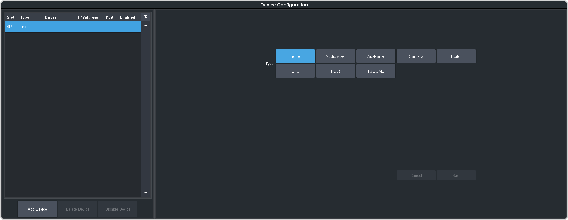
-
Click the SP slot on the table to select the serial port.
Tip: Click Disable Device to temporarily disable the selected device.
-
In the Type area click Editor.
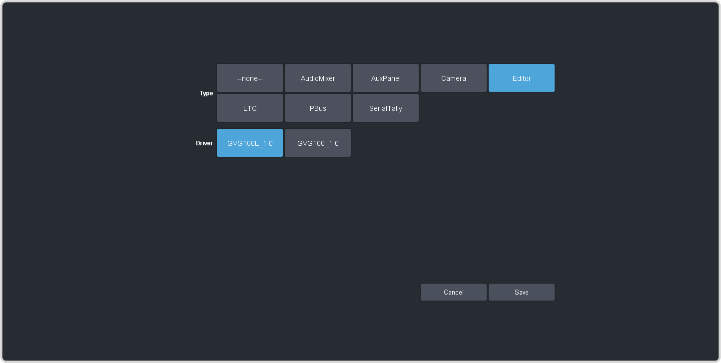
-
In the Driver area click the driver you want to use for your device.
- GVG100L_1.0 — supports the legacy set of GVG100 editor commands
- GVG100_1.0 — supports the custom Ross® superset of GVG100 editor commands
- Click Save.
GVG100 Editor Setup
Refer to the documentation that came with your editor for information on setting up your editor to communicate with the switcher. To communicate with the switcher, you must use the following communication settings:
- 38.4k Baud
- 8 Data Bits
- 1 Stop Bit
- Odd Parity