
Yamaha®
The information in this document applies to the 01V96 and DM1000 using the openGear® SMC-9901 Serial to MIDI Converter.
Refer to the documentation that came with the SMC-9901 Serial to MIDI Converter for setup information.
Cable Connections
The audio mixer connects to the switcher through an openGear® SMC-9901 Serial to MIDI Converter connected directly to the switcher over RS-422.
SMC-9901 to Carbonite Cabling
A serial cable is used to connect the SMC-9901 to the switcher.
| SMC-9901 (Serial Port) | Carbonite (Serial Port) |
|---|---|
.png)
|
.png)
|
| 2 (Tx-) | 6 (Rx-) |
| 3 (Rx+) | 1 (Tx+) |
| 7 (Tx+) | 3 (Rx+) |
| 8 (Rx-) | 2 (Tx-) |
| 5 (GND) | 7 (GND) |
SMC-9901 to Nport® 5150A Cabling
A serial cable is used to connect the SMC-9901 to the Nport® 5150A. A standard ethernet connection is used between the Nport® 5150A and the switcher.
| SMC-9901 (Serial Port) | Nport® 5150A (Port 1) |
|---|---|
|
|
.png)
|
| 2 (Tx-) | 4 (Rx-) |
| 3 (Rx+) | 2 (Tx+) |
| 7 (Tx+) | 3 (Rx+) |
| 8 (Rx-) | 1 (Tx-) |
| 5 (GND) | 5 (GND) |
SMC-9901 to DeviceMaster® Cabling
A serial cable is used to connect the SMC-9901 to the DeviceMaster®. A standard ethernet connection is used between the DeviceMaster® and the switcher.
| SMC-9901 (Serial Port) | DeviceMaster® (Port 1) |
|---|---|
|
|
|
| 2 (Tx-) | 2 (Rx-) |
| 3 (Rx+) | 7 (Tx+) |
| 7 (Tx+) | 8 (Rx+) |
| 8 (Rx-) | 3 (Tx-) |
| 5 (GND) | 5 (GND) |
Switcher Communication Setup
The switcher must be set up to communicate with the audio mixer using either serial or ethernet communications.
To Set Up Ethernet Communications
This procedure varies, depending on the model of Yamaha® mixer you are setting up.
-
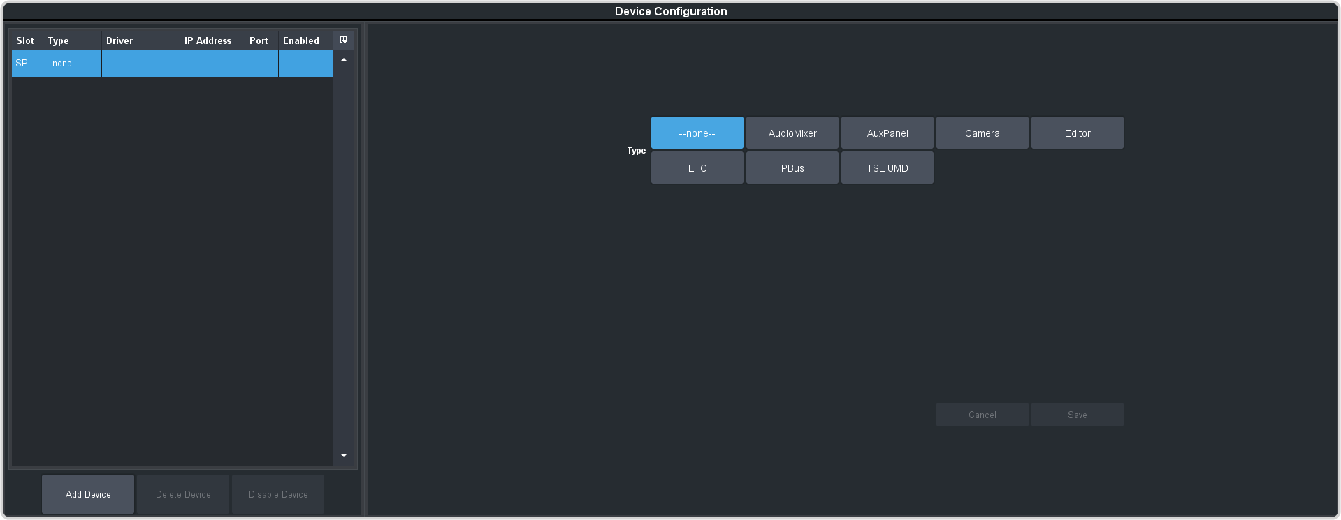
Click Navigation Menu > Configuration > Devices.
-
Click Add Device.
Tip: Click Disable Device to temporarily disable the selected device.
-
Click Slot and select a free ethernet device slot.
Tip: A slot does not appear in the list if it is being used. You can click on the slot in the table on the left to edit the device settings.
-
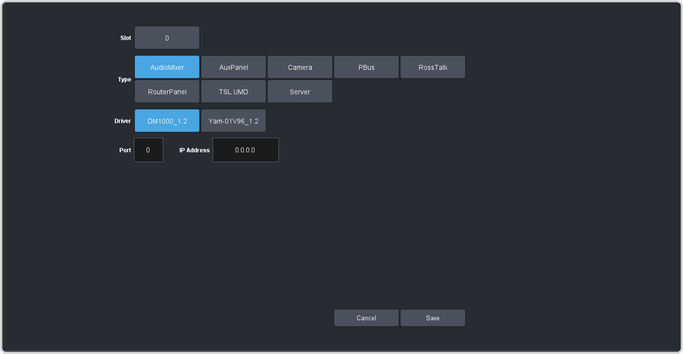
In the Type area click Audio Mixer.
-
Select the following setting for your device:
Setting Selection Driver - Yamaha® DM1000 — select DM1000_1.2
- Yamaha® 01V96 — select y01V96_1.2
IP Address Enter the IP address of the device you are connecting to. Port Enter the network port on the on the device you want to connect to. Tip: If you are using multiple RossTalk connections, it is recommended that you increment the port number for each device. - Click Save.
Switcher Video Setup
The switcher must be set up to associate the audio channels on the mixer with video sources coming into the switcher for audio follow video (AFV) functionality.
To Assign an Audio Channel to a Video Input
Repeat this procedure to add multiple audio channels to a video source.
-
Click Navigation Menu > Configuration > Inputs > External.
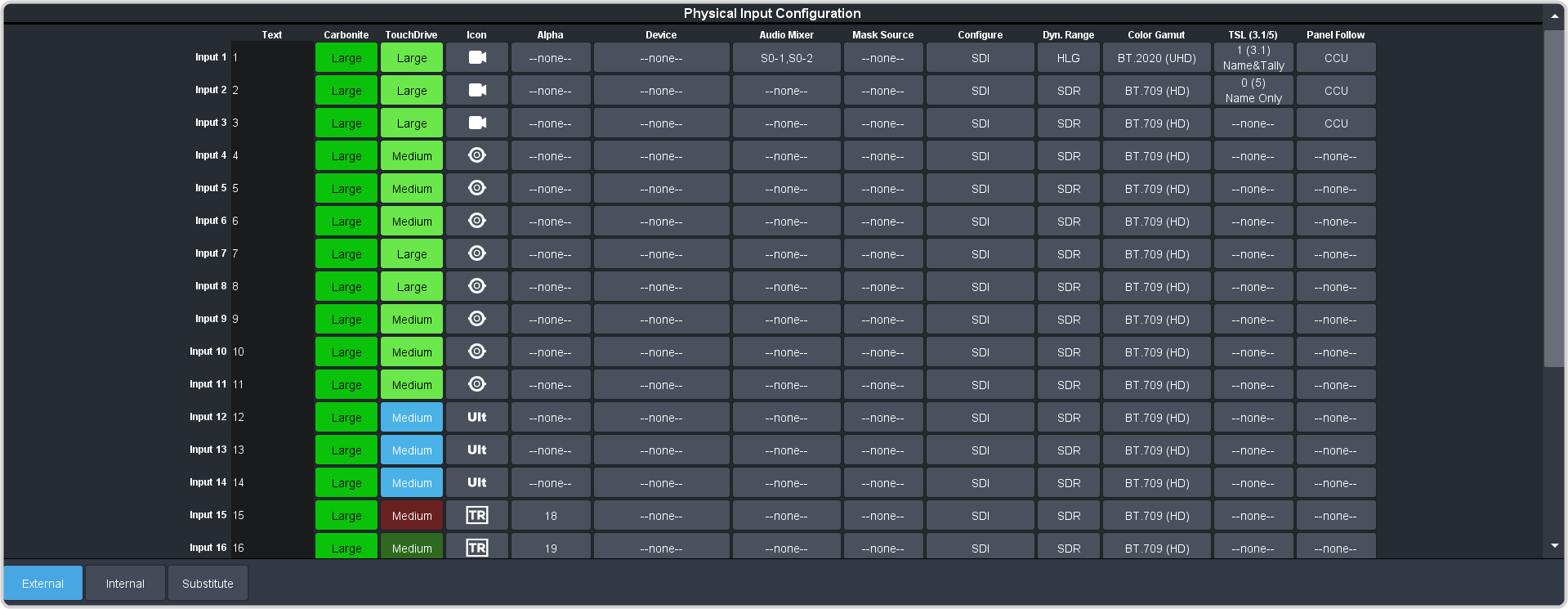
- Click the Audio Mixer button for the video source that you want to assign audio channels to.
-
Click Add Channel.

-
Select the following setting for your device:
Setting Selection Slot Select the audio mixer that you want to assign an audio channel from. Channel Select the audio channel that you want to assign to the video source. Level Select the default audio level for the selected audio channel. Latch Select whether the switcher brings an audio channel on at the same level it was last set to for the selected video source (Yes), or it always uses the default audio level (No). Tip: Click Add Channel again to associate multiple audio channels to the video input.
Nport® 5150A Setup
Refer to the documentation that came with your Nport® 5150A for safety and setup information.
Use the NPort Administrator application to set up the Nport® 5150A as listed below.
Operation Mode
- Operation Mode — TCP Server Mode
- Max Connection — 2 (or more)
Serial Parameters
- Baudrate — 38400
- Data bits — 8
- Stop bits — 1
- Parity — None
- Flow control — RTS/CTS
- FIFO — Enable
- Interface — RS-422
Ethernet Parameters
- IP Address — the default IP address is shown on the bottom of the device
- Local TCP Port — 4001 (default)
DeviceMaster® Setup
Refer to the documentation that came with the DeviceMaster® for information on using the Comtrol® PortVision® software to set up the DeviceMaster®.
If you are using a Cisco Systems® brand router, or switch, to connect the Comtrol® DeviceMaster® to the switcher, you must disable the BPDU Guard on the router, or switch, to ensure proper communications.
Audio Mixer Setup
The audio mixer must be set up to accept commands from the switcher over MIDI.
To Set Up the 01V96
- Press the DIO/SETUP function button on the Display Access Group.
- Press the MIDI/HOST tab.
-
Use the cursor buttons to navigate to the following (you must press ENTER after each
selection):
- Set Tx PORT to MIDI.
- Set Rx PORT to MIDI.
- Press the MIDI function button on the Display Access Group.
- Press the SETUP tab.
-
Use the cursor buttons to navigate to the following:
Tx Rx Omni Echo Value Channel 1 1 -- -- -- Program Change ON ON OFF OFF -- Control Change OFF OFF OFF -- -- Param Change ON ON -- OFF -- Bulk -- OFF -- -- -- Other Commands -- -- -- OFF -- Fader Resolution -- -- -- -- LOW
To Set Up the DM1000
- Press the SETUP function button on the Display Access Group.
- Press the MIDI/HOST tab.
-
Use the cursor buttons to navigate to the following (you must press ENTER after each
selection):
- Set TO SERIAL HOST to PC-2.
- Set Rx PORT to MIDI.
- Set Tx PORT to MIDI.
- Press the MIDI function button on the Display Access Group.
- Press the SETUP tab.
-
Use the cursor buttons to navigate to the RECEIVE section and set the following:
Tx Rx Omni Echo Value Channel 1 1 -- -- -- Program Change ON ON OFF OFF -- Control Change ON ON OFF OFF -- Param Change ON ON -- OFF -- Bulk -- OFF -- -- -- Other Commands -- -- -- OFF -- Fader Resolution -- -- -- -- LOW