TouchDrive Control Panels
Each TouchDrive control panel is made up of a number of distinct areas that control different aspects of the switcher. Some of these areas may vary in size or function, depending on the control panel you have.
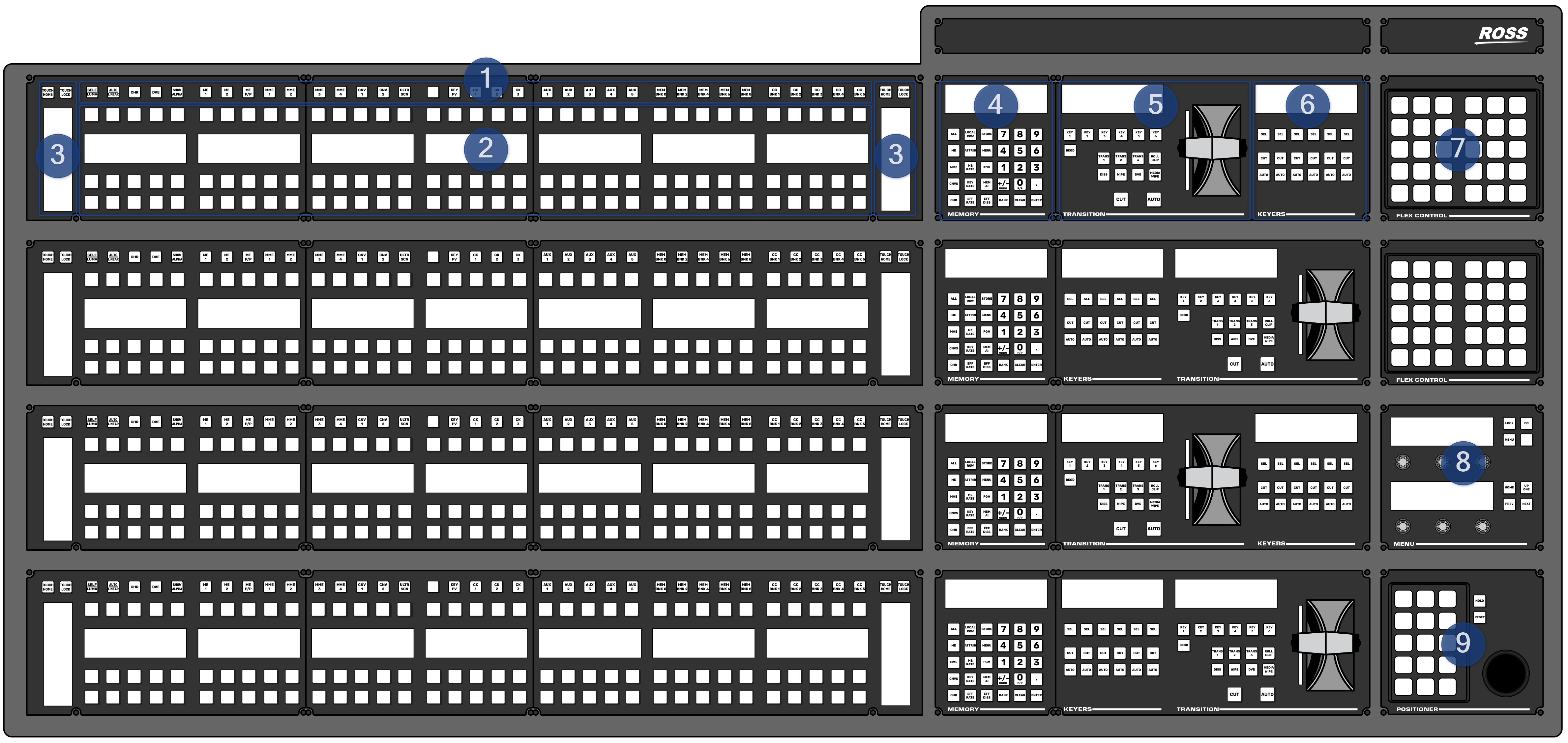
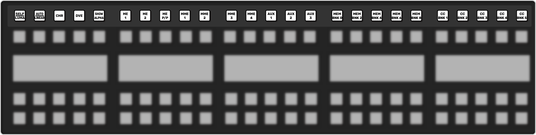
1. User Buttons
The default user button assignments differ between Carbonite and Acuity®. All the user buttons can be assigned to different functions.
Carbonite Configuration
These buttons can be assigned to various functions or buses on the switcher. The default assignments are labelled on the buttons.
| Button | Function |
|---|---|
| SELF/LUMA | Assign Self as the key type for the selected key. |
| AUTO/LINEAR | Assign Auto Select as the key type for the selected key. |
| CHR | Assign the key bus to chroma key 1. Press and hold the button to select a different chroma key. |
| DVE | Assign DVE as the key type for the selected key. |
| SHOW ALPHA | View the black and white alpha signal for the selected keyer. This alpha signal is routed to the preview output of the selected ME. Press and hold to turn on the show alpha feature. Double-press the button to latch the show alpha state until the button is pressed again. |
| ME X | Assign the panel row to ME X. Press and hold the button to select a different ME. |
| MME X | Assign the panel row to MiniME™ X. Press and hold the button to select a different MiniME™ |
| AUX x | Assign the key bus to aux bus X. Press and hold the AUX button and use the source buttons on the keyer row to select the aux you want to use. |
| MEM BNK X | Recall a memory using the source buttons on the key bus. Press the MEM BNK button for the memory bank you want to recall a memory from and then press the button on the key bus for the memory you want to recall. Press and hold the MEM BNK button to select a different bank using the source buttons on the key bus. |
| CC BNK X | Run a custom control using the source buttons on the key bus. Press the CC BNK button for the bank you want to run a CC from and then press the button on the key bus for the CC you want to run. Press and hold the CC BNK button to select a different bank using the source buttons on the key bus. |
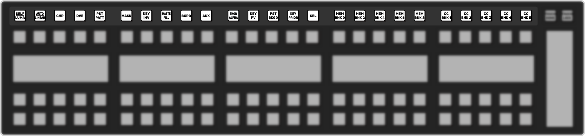
Acuity® Configuration
These buttons can be assigned to various functions or buses on the switcher. The default assignments are labelled on the buttons.
| Button | Function |
|---|---|
| SELF/LUMA | Assign Self as the key type for the selected key. |
| AUTO/LINEAR | Assign Auto Select as the key type for the selected key. |
| CHR | Assign Chroma Key as the key type for the selected key. |
| DVE | Assign 2D DVE as the key type for the selected key. |
| PST PATT | Assign a Preset Pattern as the key type for the selected key. |
| MASK | Turn on the Mask function. |
| KEY INV | Reverses the polarity of the key alpha. For example, if a self key, such as a title camera, has white letters on a black background, the white letters will normally cut the key hole. When the key invert feature is used, the polarity of the key is inverted so that black lettering is used to cut the hole. |
| MATTE FILL | Fill the selected keyer with a matte color. |
| BORD | Apply a border to the selected keyer. When pressed, the border menu is displayed, and the last selected border is applied. Press the button again to turn the border off. |
| AUX | Press and hold the AUX button and use the source buttons on the keyer row to select the aux you want to use. |
| SHOW ALPHA | View the black and white alpha signal for the selected keyer. This alpha signal can either be routed to the main preview output of the switcher, or to the preview output of the selected ME. Press and hold the SHOW ALPHA button, for the selected keyer and ME, to show the alpha for that keyer on the preview output of the switcher, or double-press the SHOW ALPHA button to lock it on until the button is pressed again. This allows you to record the alpha signal for a selected keyer independent of the fill. |
| KEY PV | Temporarily force the program output of the selected keyer to the preview output of the switcher. The ME remains in the key preview state for as long as you hold the KEY PV button, and returns to normal as soon as you release the button. You can also double-press the KEY PV button to latch the ME in the key preview state until the button is double-pressed again. |
| PST BKGD | Insert a transition to black as the next transition without losing what is currently selected as the next transition. |
| KEY PRIOR | Change the priority of the keyers on the ME. |
| SEL | Quickly navigate to the ME Selection menu. Press and hold the SEL button and use the source buttons on the Key and Background buses to select what the panel row is assigned to. |
| MEM BNK X | Recall a memory using the source buttons on the key bus. Press the MEM BNK button for the memory bank you want to recall a memory from and then press the button on the key bus for the memory you want to recall. Press and hold the MEM BNK button to select a different bank using the source buttons on the key bus. |
| CC BNK X | Run a custom control using the source buttons on the key bus. Press the CC BNK button for the bank you want to run a CC from and then press the button on the key bus for the CC you want to run. Press and hold the CC BNK button to select a different bank using the source buttons on the key bus. |
2. Video Source Buses
Each panel row has three buses of video source buttons (Keyer, Background, and Preset). When the panel row is assigned to a ME, MiniME™, or MultiScreen each bus of buttons is assigned to a video bus. If the panel row is assigned to a chroma key or aux bus, the key bus row is assigned to that video bus while the background and preset buses remain assigned to the previous buses.
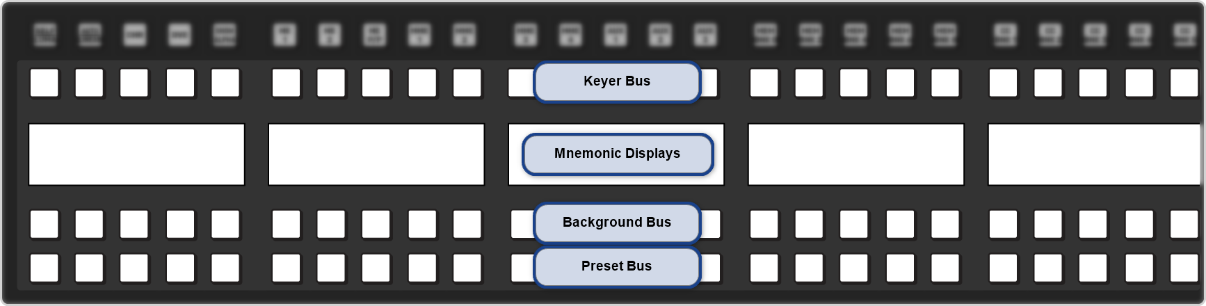
The mnemonic displays show the video sources that are assigned to the buttons on the keyer row and background/preset row.
3. Row Control
The row control menu at the end of the panel row allows you to see what the row and buses are assigned to, as well as control some aspects of the row.
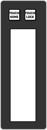
The TOUCH HOME and TOUCH LOCK buttons are used to return the display to the Home menu (TOUCH HOME) and lock the display and mnemonics so that it can't be accidentally tapped (TOUCH LOCK).
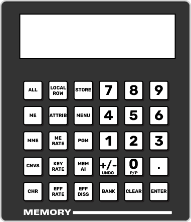
4. Memory Area
The function of the buttons on the Memory area differ between Carbonite and Acuity®.
Carbonite Configuration
The memory area is used to store and recall memories, and to enter the various transition rates used by the switcher. The buttons in the left column assign the memory area to the various ME, MiniME™, MultiScreen, or chroma key resources of the switcher.
| Button | Function |
|---|---|
| ALL | Select all ME, MiniME™, MultiScreen, and chroma key inclusions for with the memory action. Press ALL to include all the elements with the memory store or recall. The inclusions are shown on the display. |
| ME | Select only specific ME inclusions for the memory action. Press and hold ME and press the number buttons to add or remove an element from the inclusions for the memory store or recall. The inclusions are shown on the display. |
| MME | Select only specific MiniME™ inclusions for the memory action. Press and hold MME and press the number buttons to add or remove an element from the inclusions for the memory store or recall. The inclusions are shown on the display. |
| CNVS | Select only specific MultiScreen inclusions for the memory action. Press and hold CNVS and press the number buttons to add or remove an element from the inclusions for the memory store or recall. The inclusions are shown on the display. |
| CHR | Select only specific chroma key inclusions for the memory action. Press and hold CHR and press the number buttons to add or remove an element from the inclusions for the memory store or recall. The inclusions are shown on the display. |
| LOCAL ROW | Select only the ME that the panel row is assigned to as the inclusion for the memory action. |
| ATTRIB | Jump to the Memory Attributes page in DashBoard. |
| ME RATE | Set the background transition rate for the ME that the panel row is assigned to. Press ME RATE and use the keypad to enter the new rate. The rate is shown on the display in the Transition area. |
| KEY RATE | Set the key only transition rate for the ME that the panel row is assigned to. Press KEY RATE and use the keypad to enter the new rate. The rate is shown on the display in the Keyer area for each individual key. |
| EFF RATE | Set the effects dissolve rate. Press EFF RATE and use the keypad to enter the new rate. |
| STORE | Set the Memory area to store mode. By default, the Memory area is in Recall mode. Press STORE (On) to put the Memory area in Store mode to store
memories. Tip: Press and hold STORE and press LOCAL ROW to reset only the row
you are working on or ALL to reset all rows. |
| MENU | Set the Memory area to follow the menu selections. This allows you to use the keypad to select wipe pattern or media items. Press MENU (On) to turn the follow on. |
| PGM | Set the Program recall mode where all elements of the memory are recalled as they are stored. |
| MEM AI | Set the Memory AI mode where current on-air elements are unchanged and the transition area is configured to take the on-air elements of the memory on-air with the next transition. |
| EFF DISS | Turn on the Effects Dissolve effect for the memory recall. On-air elements are transitioned to the elements stored in the memory. The time it takes to go from the current elements to the elements in the memory is set with the EFF RATE. |
| +/- UNDO | Undo the last memory recall. When entering number values with the keypad, press +/- to toggle between positive and negative values. |
| BANK | Select the memory bank you want to use. Press and hold the BANK button and press the number for the custom control or memory bank you want to access. |
| CLEAR | Clear the current value being entered. For example, enter an incorrect value on the keypad and press CLEAR to remove it. |
| ENTER | Commit the currently entered value. For example, enter a new key rate using the keypad and press ENTER to apply it. |
| 0-9 | The keypad numbers are used to select ME inclusions as well as enter rate values or clip ids. |
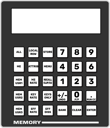
Acuity® Configuration
The memory area is used to store and recall memories, and to enter the various transition rates used by the switcher. The buttons in the left column assign the memory area to a specific ME.
| Button | Function |
|---|---|
| ALL | Select all ME inclusions for with the memory action. Press ALL to include all the elements with the memory store or recall. The inclusions are shown on the display. |
| ME | Select only specific ME inclusions for the memory action. Press and hold ME and press the number buttons to add or remove an element from the inclusions for the memory store or recall. The inclusions are shown on the display. |
| MEM USR# | User assignable buttons. You can assign any function to these buttons from the Personality menu. |
| LOCAL ROW | Select only the ME that the panel row is assigned to as the inclusion for the memory action. |
| ATTRIB | Allows you to view the memory attributes menu, or override the attributes stored with the memory with the default attribute settings. To override attributes, press and hold the ATTRIB button while recalling the memory. |
| ME RATE | Set the background transition rate for the ME that the panel row is assigned to. Press ME RATE and use the keypad to enter the new rate. The rate is shown on the display in the Transition area. |
| KEY RATE | Set the key only transition rate for the ME that the panel row is assigned to. Press KEY RATE and use the keypad to enter the new rate. The rate is shown on the display in the Keyer area for each individual key. |
| EFF RATE | Set the effects dissolve rate. Press EFF RATE and use the keypad to enter the new rate. |
| STORE | Set the Memory area to store mode. By default, the Memory area is in Recall mode. Press STORE (On) to put the Memory area in Store mode to store
memories. Tip: Press and hold STORE and press LOCAL ROW to reset only the row
you are working on or ALL to reset all rows. |
| MENU | Have the Memory area follow menu selections. Press the MENU button on a Memory area to have that Memory area follow menu selections, such as wipe pattern, DVE sequence, or media item selection. |
| RECALL CLIP/CC | Allows you to either recall a clip on the selected device using a Clip ID or Clip Number by entering it using the keypad, or run a custom control by entering the bank and custom control number. The functionality of the Recall Clip/CC button is set using the CC Global Recall personality option. |
| KEYS ONLY | Recall a memory on a panel row that does not include the program and preset bus selections. Only the keyer selections are recalled. |
| EFF DISS | Turn on the Effects Dissolve effect for the memory recall. On-air elements are transitioned to the elements stored in the memory. The time it takes to go from the current elements to the elements in the memory is set with the EFF RATE. |
| +/- UNDO | Undo the last memory recall. The UNDO button lights up after each memory recall, indicating that the action can be undone. If you perform 10 or more button presses after the memory recall, the UNDO button goes out, and the memory can no longer be recalled. When entering number values with the keypad, press +/- to toggle between positive and negative values. |
| BANK | Select the memory bank you want to use. Press and hold the BANK button and press the number for the custom control or memory bank you want to access. |
| CLEAR | Clear your current entry. For example, if you are entering a memory register to recall, but then decide not to recall the memory, you can press the CLEAR button to return to the previous state. |
| ENTER | Commit the currently entered value. For example, enter a new key rate using the keypad and press ENTER to apply it. |
| RUN CC | Run a custom control that you have recalled using the RECALL CC button. |
| 0-9 | The keypad numbers are used to select ME inclusions as well as enter rate values or clip ids. |
5. Transition Area
The transition area is used to select which video source buses will be included in the next transition and what type of transition will be performed. The Cut and Auto buttons and the fader are used to perform transitions.
The function of the buttons on the Transition area differ between Carbonite and Acuity®.
Carbonite Configuration
| Button | Function |
|---|---|
| BKGD | Include the background in the next transition. |
| KEY X | Include a key with the next transition. |
| TRANS X | User assignable buttons. |
| ROLL CLIP | Tie the playout of a clip to the next transition, or have the clip play immediately. Roll clip only works with external devices that are being controlled by the switcher. |
| DISS | Select a dissolve as the next transition type. |
| WIPE | Select a wipe as the next transition type. |
| DVE | Select a DVE wipe as the next transition type. |
| MEDIA WIPE | Select a MediaWipe as the next transition type. |
Acuity® Configuration
| Button | Function |
|---|---|
| BKGD | Include the background in the next transition. |
| KEY X | Include a key with the next transition. |
| PGM A | Assign the Transition module and buses on that row to Program A of the configurable program output. |
| PGM B | Assign the Transition module and buses on that row to Program B of the configurable program output. |
| TRANS LIMIT | Set the point where a transition will stop. This allows you to have a transition proceed only half way and stop. The next transition is performed from that stop point, back to the original starting point. |
| ROLL CLIP | Tie the playout of a clip to the next transition, or have the clip play immediately. Roll clip only works with external devices that are being controlled by the switcher. |
| DISS | Select a dissolve as the next transition type. |
| WIPE | Select a wipe as the next transition type. |
| DVE | Select a DVE wipe as the next transition type. |
| MEDIA WIPE | Not used at this time. |
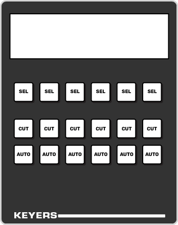
6. Keyer Area
The keyer area is used to select and independently transition keys. The display shows the on-air status of each key and the source currently selected on that key. Used the CUT and AUTO buttons to perform cuts or auto transitions on keys directly, without having to include them as part of the next transition.
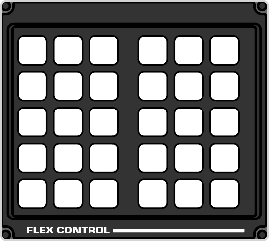
7. Flex Control Area
The Flex Control area is made up of a user selectable buttons, much like on the panel row, that can be have various functions assigned to them. The functions that can be assigned to the buttons depends on the switcher the panel is connected to.
The default user button assignments differ between Carbonite and Acuity®. All the user buttons can be assigned to different functions.
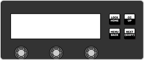
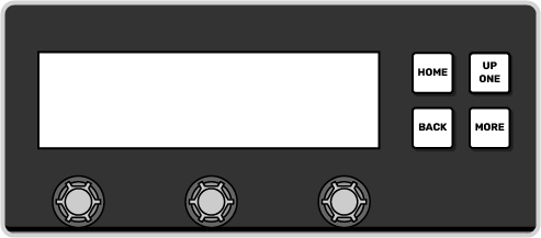
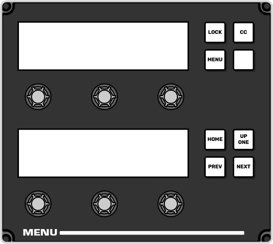
8. 3-Knob Menu
The buttons next to the 3-knob menu differ between Carbonite and Acuity®. The display and the knobs in both systems follow the main menu selections.
Carbonite
The 3-knob menu is used to access the legacy menu system of the switcher, as well as some auto-follow functions attached to video source selections.
Acuity®
The 3-knob menu provided physical knobs for menu selections. The 3-knob menu auto-follows the Main menu.
TD3 and 4 Panels
The TD3 and TD4 panels have a stacked version of the 3-knob menu. The menu operates the same as on the other panels, but can show two menu pages at the same time. For Acuity® the top display shows the upper menu area and the bottom display the lower menu area.
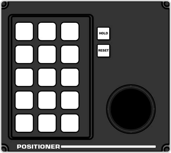
9. Positioner
The positioner is used to position and size keys in the DVE, control some wipe, border, and wash parameters, as well as control some external devices.
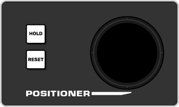
The HOLD and RESET buttons are used to lock the positioner to the current assignment (HOLD) or used with other panel buttons to reset different areas (RESET).
The TD3 and TD4 panels have an additional set of user selectable buttons, the same as on the Flex Control area. The functions that can be assigned to the buttons depends on the switcher the panel is connected to.
The default user button assignments differ between Carbonite and Acuity®. All the user buttons can be assigned to different functions.